Ok, so far this first turnout is kicking my ass. I’ll produce a real “how to build these turnouts” article — when I really know to build one of these turnouts. Right now, I’m severely learning. Think of this as a “still clinging to the cliff” kind of report although I’m still having fun and I’m still happy about choosing the Central Valley turnout kits.
Central Valley Model Works (CVMW) has been around since the late 1940’s. However, their CVT system of styrene tie strips and turnout kits is relatively new. I’m building most of my track using Micro Engineering code 83 flex track. Code 83 you say? Yes, I have some old Rivarrosi and IHC engines that I actually like, and code 70 is too low for their (way too big) flanges so code 83 it is – good enough.
For turnouts I originally intended to use Walthers/Shinohara code 83 #4’s – these are excellent turnouts but were completely out of stock for the foreseeable future during the end of 2005 when I was putting all my materials together. I procrastinate enough at the best of times and having any real excuse to stop forward progress is simply too risky so I shopped around for an immediately available alternative. The CVT turnouts had been on my short list and they were available. I ordered straight from CVMW and they arrived quickly.
The pros, cons, and costs of the CVT turnouts are obvious:
Pro: great detail – museum quality looks.
Con: you need to build them yourself and I feel it’s fair to say that they are one notch more difficult than the normal way one would scratch build a turnout and obviously way more work than a pre-built turnout.
Cost: very comparable with other turnouts. Not really a factor in the decision.
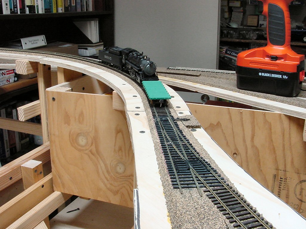
I picked a spot on my layout to lay the first turnout.
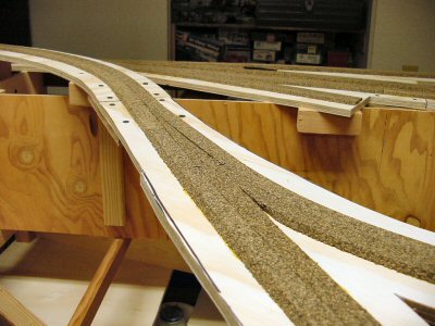
An easily accessible simple siding on the mainline. The CVT instructions (yes, I actually read them) say to start by gluing down the tie strip onto the layout. However since this was my first one I chose to do a quite a bit of dry fitting on the workbench before doing anything on the layout.
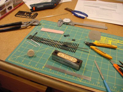
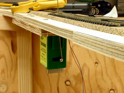
I made a drilling template out of ¼ masonite and drilled the “throw” hole and holes for feeder wires. Then glued the tie block down with contact cement and glued down a small piece of roadbed to be the foundation for the switch stand.
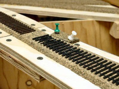
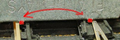
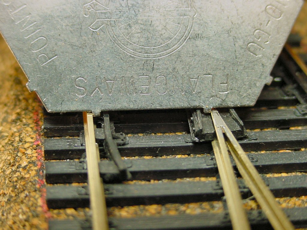
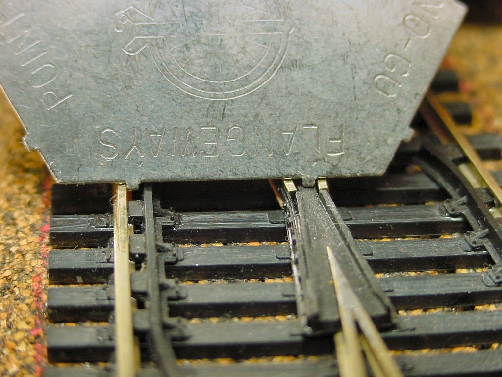
I’d love to say “then I just attached the rails and away we go” but there has been a lot of learning. Central Valley recommends barge cement diluted with MEK to attach the rails. I tried it and this is a really good recommendation — but there is still some art involved.
After some work I got my first turnout installed and working.
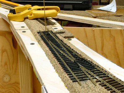
I’m using Tortoise switch machines and I’m using 1/16” square brass rod to throw the turnout.