March 2006
Monthly Archive
Sun 19 Mar 2006
When I was younger I used to go climb and play on this little ship. Many years later (around 1982) I got a picture of it. Unfortunately, I only had a cheapo camera and the boat has since collapsed.

I found the print (only 3×5 inches) and scanned it at 300 dpi optical about ten years ago. I’ve always thought she’d make a great model for a RR/Wharf scene.
I’ve never been able to find any reference to her but she had “MARIN” faintly painted on her bow.
I think the Marin worked as a small freight and passenger ship. The main deck was very heavy construction: three layers of 2″ planking at skewed angles with asphalt and fine gravel coating on top. There was no evidence of any forward bulwark. In other photos of similar boats you see removable open rails on the forward deck.
It looked like cargo was loaded on and off the foredeck and stored as far back as the area under the main cabin. The part of the main deck covered by the upper cabin was open except for 3 or 4 support posts up the middle. One of these can be seen directly under the front of the wheelhouse.
The engine and hardware were long gone. There were indications that two cylindrical fuel tanks were mounted under the main deck on either side leaving room far a good size in-line gas/diesel engine mounted above the keel, towards the stern. She had a single screw and rudder.
There was only four feet of headroom inside the flat-bottomed hull between the frames and the deck beams under the main deck. I think she was built as a motor-boat (not converted from steam) since boilers usually had to be in the middle of the hull and there really wasn’t head room on the MARIN below the main deck.
The wheelhouse was elevated about three feet above the upper deck level. Inside, the wheelhouse had a large “shelf” across the after portion which was actually the roof of the Skipper’s cabin. The upper cabin had a small captain’s cabin forward that went full width. The remainder was undivided and had benches along the walls facing inwards.
The boat used to be about 100 feet from the water on the north shore of Bodega Bay, California. The location at Mapquest (or other map website) may be found by entering the following location: Bay Flat Rd & Whaleship Rd, Bodega Bay, CA 94923
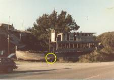
Measurements: The yellow circle shows where I placed a story pole on the ship to aid in measuring it from the photo. It was painted white and black on the belt rail of the hull, just forward of directly below the front of the wheelhouse. It is marked in feet with the first and third feet white and the middle foot black. The middle foot also has six inches marked in alternate white/black patches (these are slightly below the resolution of the camera).
I estimate the length to be about 60 feet, beam almost 20 feet.
Sat 4 Mar 2006
Ok, so far this first turnout is kicking my ass. I’ll produce a real “how to build these turnouts” article — when I really know to build one of these turnouts. Right now, I’m severely learning. Think of this as a “still clinging to the cliff” kind of report although I’m still having fun and I’m still happy about choosing the Central Valley turnout kits.
Central Valley Model Works (CVMW) has been around since the late 1940’s. However, their CVT system of styrene tie strips and turnout kits is relatively new. I’m building most of my track using Micro Engineering code 83 flex track. Code 83 you say? Yes, I have some old Rivarrosi and IHC engines that I actually like, and code 70 is too low for their (way too big) flanges so code 83 it is – good enough.
For turnouts I originally intended to use Walthers/Shinohara code 83 #4’s – these are excellent turnouts but were completely out of stock for the foreseeable future during the end of 2005 when I was putting all my materials together. I procrastinate enough at the best of times and having any real excuse to stop forward progress is simply too risky so I shopped around for an immediately available alternative. The CVT turnouts had been on my short list and they were available. I ordered straight from CVMW and they arrived quickly.
The pros, cons, and costs of the CVT turnouts are obvious:
Pro: great detail – museum quality looks.
Con: you need to build them yourself and I feel it’s fair to say that they are one notch more difficult than the normal way one would scratch build a turnout and obviously way more work than a pre-built turnout.
Cost: very comparable with other turnouts. Not really a factor in the decision.
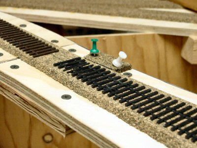
I picked a spot on my layout to lay the first turnout.
An easily accessible simple siding on the mainline. The CVT instructions (yes, I actually read them) say to start by gluing down the tie strip onto the layout. However since this was my first one I chose to do a quite a bit of dry fitting on the workbench before doing anything on the layout.
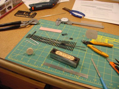
I made a drilling template out of ¼ masonite and drilled the “throw” hole and holes for feeder wires. Then glued the tie block down with contact cement and glued down a small piece of roadbed to be the foundation for the switch stand.
I’d love to say “then I just attached the rails and away we go” but there has been a lot of learning. Central Valley recommends barge cement diluted with MEK to attach the rails. I tried it and this is a really good recommendation — but there is still some art involved.
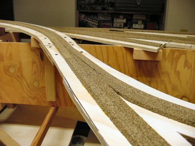
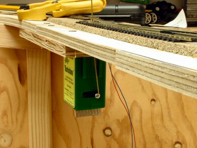
After some work I got my first turnout installed and working.
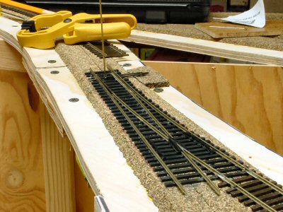
I’m using Tortoise switch machines and I’m using 1/16” square brass rod to throw the turnout.
Fri 3 Mar 2006
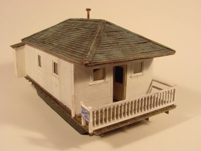
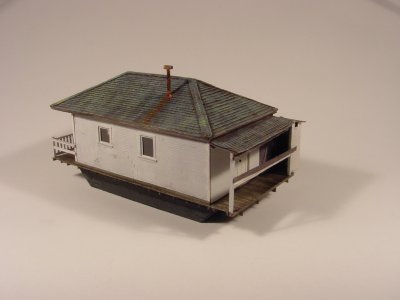
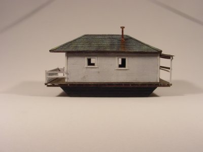
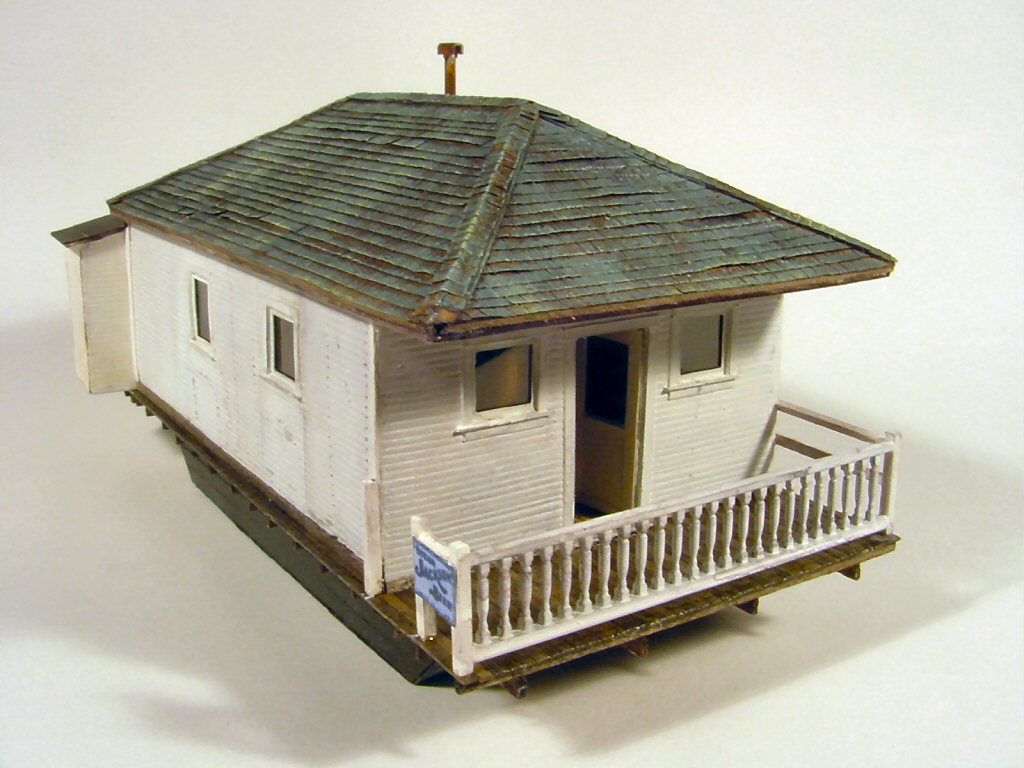
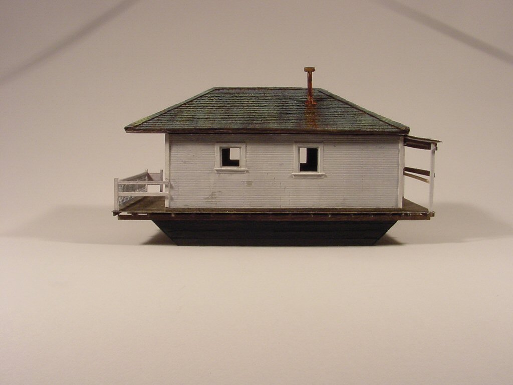
The Tiburon Railroad-Ferry Depot Museum is building an HO scale model of the Tiburon railroad yard of the Northwestern Pacific Railroad as it was in 1909. After several meetings with the the permanent staff I was informally commissioned to build some of the structures starting with “Ark Number 4.”
“Arks” are local (Marin county, California) slang for what were more commonly known around the country as “shanty boats.” Around the 1880′s and 90′s it became very popular to vacation in home-made houseboats around the San Francisco Bay. Known locally as “arks,” these houseboats, every one unique, once numbered in the hundreds. None survive afloat but many were hauled up on land to serve as housing for railroad and other local workers looking for low cost “funky” housing. I plan on having many of these Arks in and around my 1920′s Tiburbon.
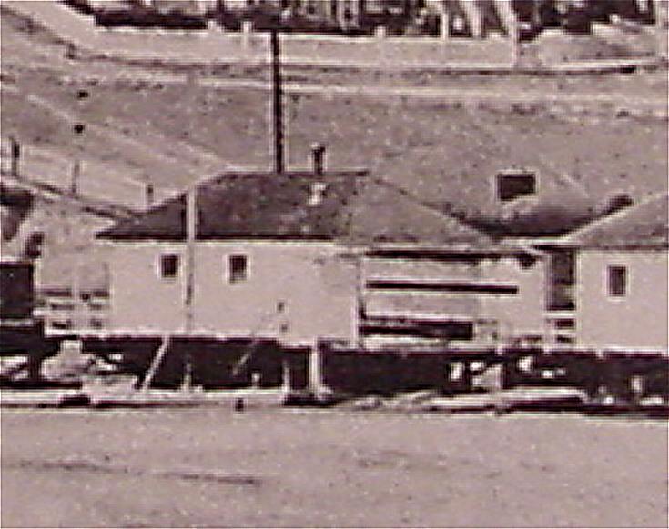
In 1909 several arks lined the Bay shore along the approach to the Tiburon yard. My sole source of data for this building were enlargements of this photo from an old post card:
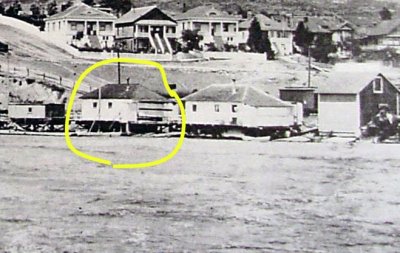
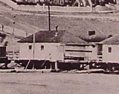
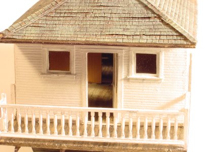
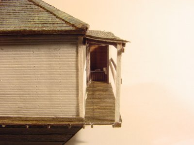
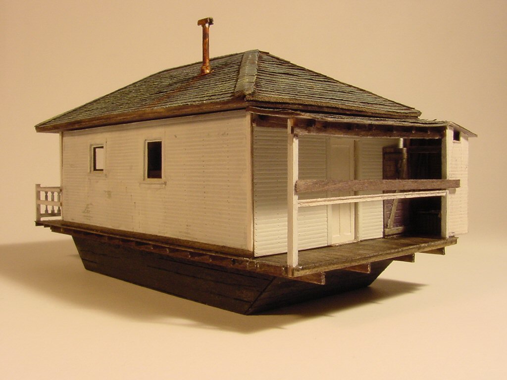
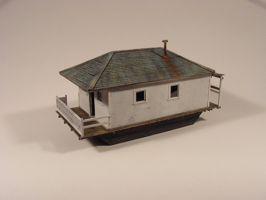
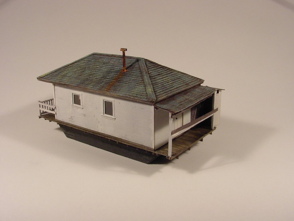
After estimating dimensions from the photo and negotiating with the museum staff how the two sides you can’t see might have looked, I proceeded to build my model. Museum requirements were to use materials compatible with at least a 50 year lifespan. Styrene is prohibited for any use but small details. White metal castings are also prohibited. In some ways this meant going back to techniques popular in the 1960′s: Strathmore, acid-free paper, wood, white glue.
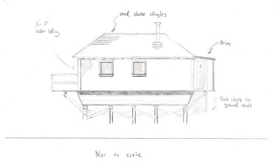
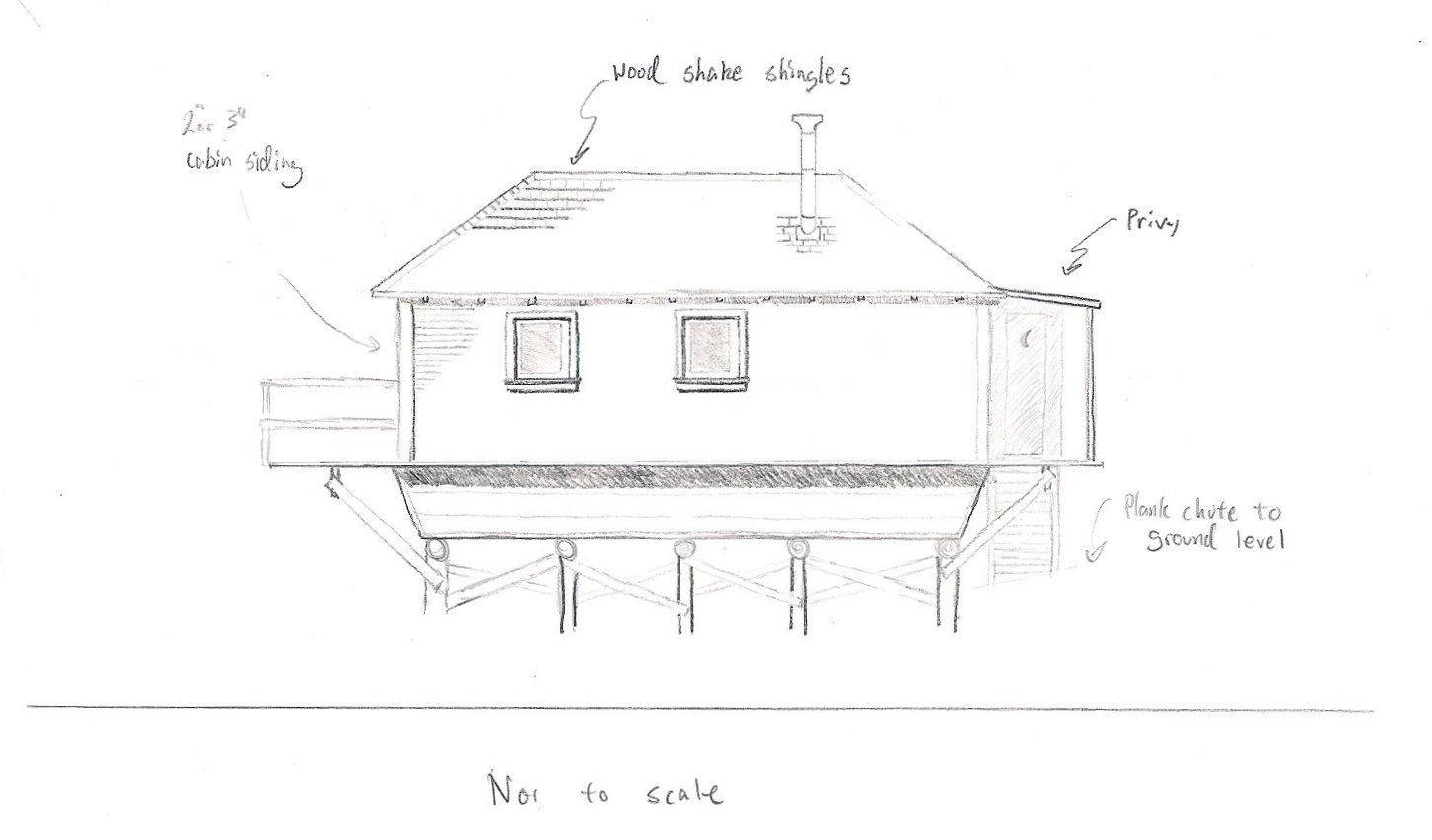
A drawing I made before construction.
I’ve been dabbling at model building (cars, trains, planes, ships) since my pre-teen years and while I have 30 years or so of experience this was my first stab at really scratchbuilding. Fortunately, I have been an avid reader of Model Railroader and the Narrow Gauge & Short Line Gazette and I drew heavily on all those articles and pictures to help me build this model.
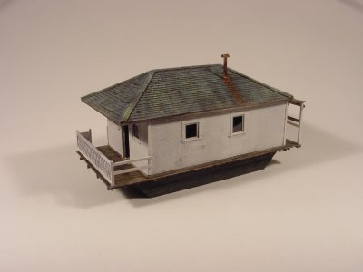
The scale is 1:87 HO. Overall dimensions are 33′ x 16′ not counting the not-so-out-outhouse. Roof is Campbell shingles on a solid wood core. Walls are hand-scribed Strathmore on a basswood core. Windows are real (damn thin) glass. Floor is board-by-board scale 1x4s.