I based my track plan on Malcolm Furlow’s 8 x 10 San Juan Central.

However I made the following changes:
- Flipped the track plan right-to-left because that fit the room I was building in better.
- Changed the plan to HO standard gauge with 18” minimum radius curves.
- Specified #5 turnouts.
- Set track “zero” height at 53-1/2” above the floor.
Because HO needs more “shoulder room” than HOn3, 18” radius turns and #5’s are bigger than the 16-18” turns and #4’s of the original plan, and because the room can fit it; I increased the size of the layout one foot on the long axis so my plan is 8’ x 11’ and is fit into a 10’ x 14’ room.
As far as the schematic layout of the tracks, curve for curve, tunnel for tunnel, bridge for bridge, the only change I made was to completely redesign the tracks at Montrose, tuning it into a seaport (Tiburbon on my layout) and add a wye behind Tincup leading off through a bookcase to staging tracks in the corner.
Like the Frenchman’s Axe: the handle replaced three times, the head replaced twice, but still the same axe – I consider my plan to be largely the same as Furlow’s SJC despite all my tweaks.
I used the 3rd PlanIt CAD system (http://www.trackplanning.com/3pi.htm) to draw my track plan. Once you are up the learning curve, CAD systems offer many benefits. I’ve had work related experience with CAD systems and while 3rd PlanIt is not flawless it is certainly good enough to have been a great help in planning the layout. Despite this I cannot recommend it to others at this time. Please see my post on this topic. There are also two good Yahoo! Groups that provide community support:
3piusers • 3pi CAD Users — not too active
http://groups.yahoo.com/group/3piusers/
3rdPlanIt • 3rd PlanIt Users Group — much more active
http://groups.yahoo.com/group/3rdPlanIt/
Where did the CAD system help me the most?
Drawing the initial plan of your layout feels really hard in a CAD system compared to pencil and paper – so much so that you can begin to wonder: is CAD is really the way to go?
The answer is YES, and here’s why: your plans change.
The initial CAD drawing may take longer to get down the first time than a cranking out a similar pencil and paper drawing but CHANGES to your plan are where the CAD simply kicks butt.
Here’s an example. I based my first draft using Walther’s Code 83 #4 turnouts. Then I went to order them. Turns out Walthers looked like they were going to be out of stock for weeks or months on those items. I changed course and decided to use Central Valley #5’s instead.
Using pencil and paper it would have taken me many hours to redraw the layout with different turnouts. In 3rd PlanIt it took less than an hour to make the change.
The other good thing a CAD system does is add up things like total track length, number of left/right turnouts, and tallies up the amount of lumber needed. I was able to get everything I needed in one trip to the lumber yard. I only had to go back once to buy one more 10-foot 1×4 because I made an oops and forgot to leave myself a long piece.
Stop when it’s Good Enough
3rd PlanIt has fairly deep terrain generating and editing capabilities but at that point in the process I made the decision that the time-to-benefit ratio was not good enough for me to go deeply into that on my plan. I used a modeling clay model of the layout to work out the 3D aspects of the scenery (I write about that here). However, I did use the CAD to make the templates for the model-of-the-model.
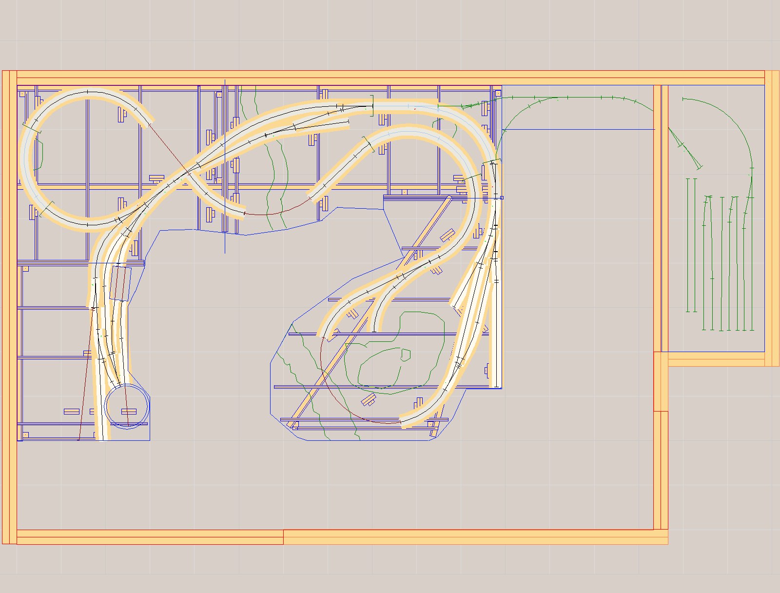
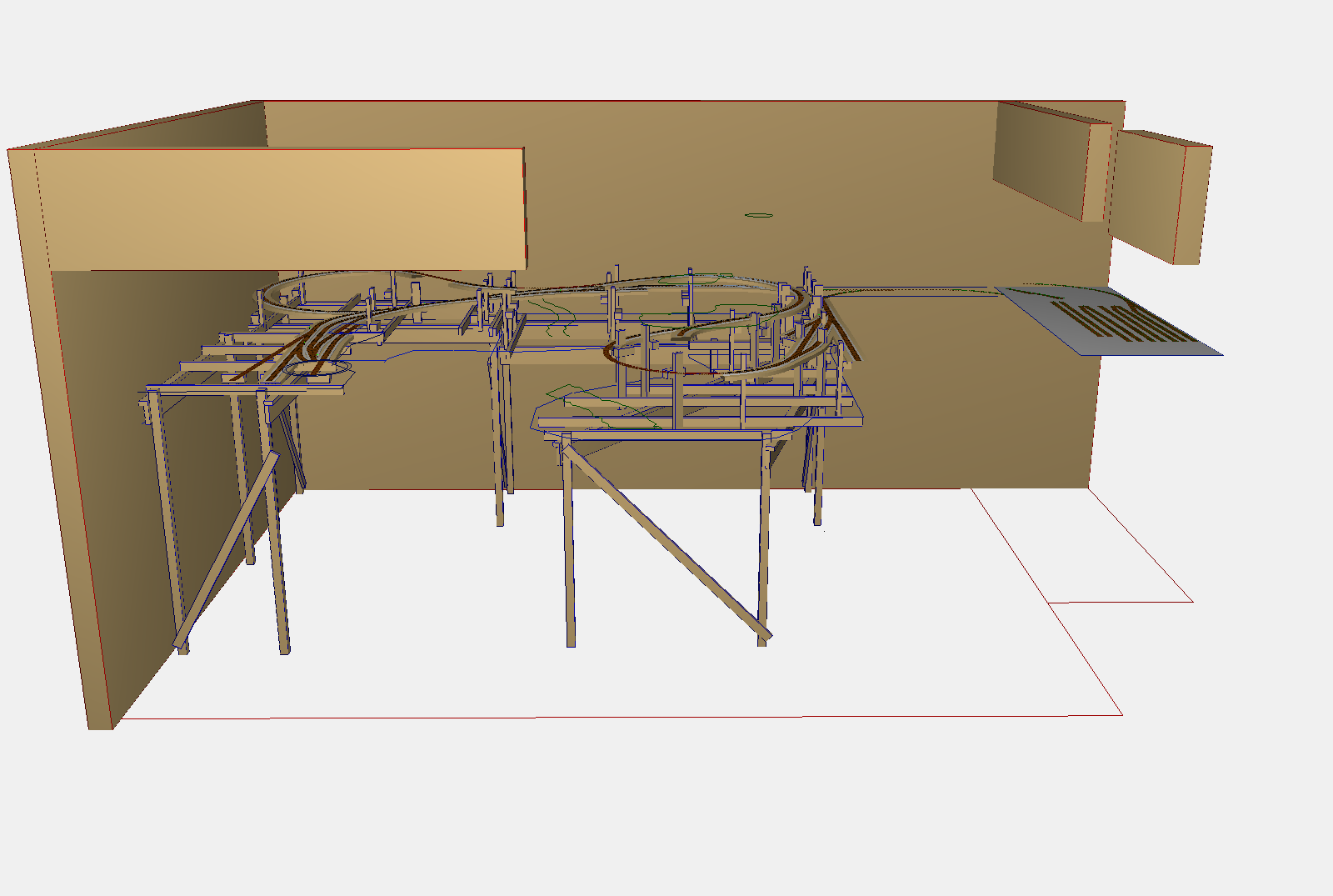
My plan and a 3D view appear below:
Please do not ask for copies of the plan.
I am unable to provide them.