March 2007
Monthly Archive
Sun 25 Mar 2007

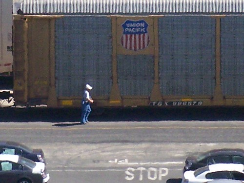
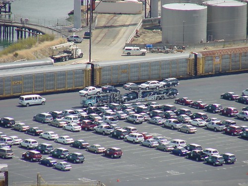
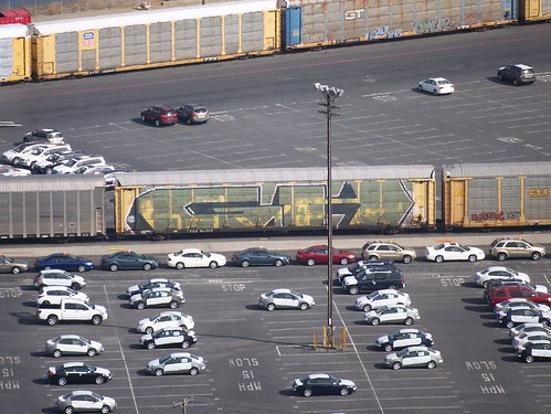
I try to go for a walk every day at lunch and I usually climb this big hill behind the office where I work. From the top of this hill I can look down on a mini-yard which is dedicated to loading and unloading auto racks with automobiles imported from Asia and other parts of the US.
This whole area of Point Richmond used to be Sante Fe trackage. BNSF now handles the moves in and out of this yard. I’m not sure if BNSF owns the yard or if it is owned by an import agency of some kind. However, the office buildings seem to have BNSF logos so this all may be owned by the railroad.
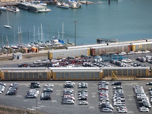
As I can see it, cars are unloaded from ships docked at piers about a half mile south of this yard (out of sight to the right in the photos) and held for a short time in a large secure parking lot. They are then driven to this yard and either loaded onto auto carrier cars or onto trucks.
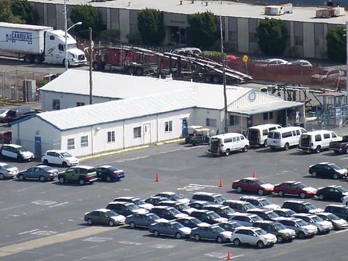
In addition, some cars arrive by rail from other parts of the US to this yard and are unloaded and then loaded onto trucks for more local delivery. Lots of traffic in and out. The cars move by being driven on their own wheels on/off ships, on/off the rail cars, and on/off trucks. There is an office where the teams of drivers work from and a bunch of vans to return drivers from their short trips between the various areas of the yard.
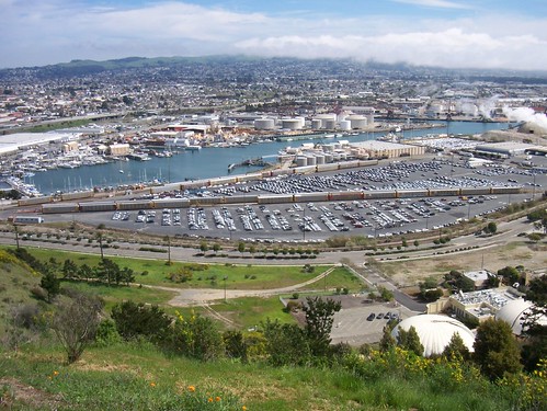
Here’s a Google Earth satellite shot of the yard.

Link to a Google Earth KMZ file to this location
I made this sketch to show schematically how the yard is laid out.
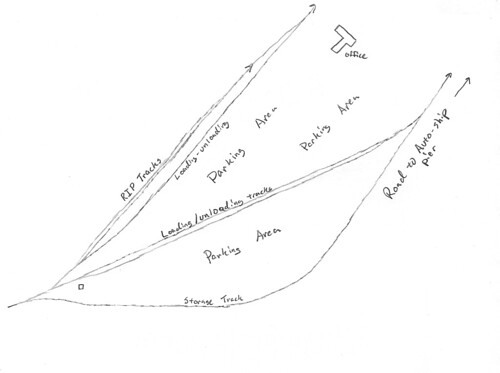
Main rail entry is gauarded by a hefty bar gate, cyclone fence gate and a small watchtower. A yard full of new cars is pretty valuable!

There’s a RIP track (Repair In Place) along the east side of the yard (the far side in these photos) where you can often find auto carriers jacked up getting minor repairs. There are several small tool sheds and a rack of welding gas and supplies nearby to support this. There are also lots of spare wheelsets of various diameters nearby.

Note that these photos were all taken from over 2000 feet away so there are heat ripple distortions in all the close-ups taken with extreme telephoto.
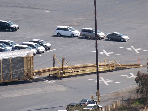
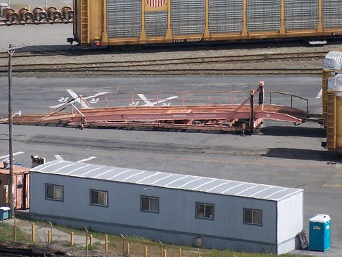
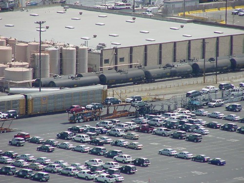
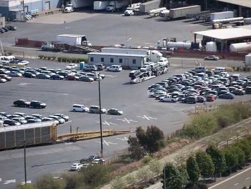
Mobile ramps are used to load/unload the cars from the auto carriers.

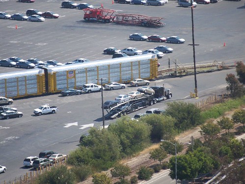
Lots of trucks coming and going.
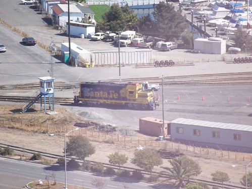
Switchers — usually this single beat-up GP35 (I’m wrong — I’m not a diesel guy and I learned that this is a GP9) still wearing Santa Fe colors comes in and shifts cars daily. There are some REALLY sharp curves in and out of this yard, something like 300 foot radius which is sharp for these huge cars. Anyway, there have been several occasions where this single switcher is not enough to pull out a long loaded string and the crew has had to either split the string and double the move or go borrow another unit to yank it out.
These moves foul all the streets nearby so I need to plan my exit from work or you can easily be stuck 20 minutes waiting for the switcher to finish its work.

Note all the little work trucks.

The graffiti work on the cars can get pretty intense.
Various office structures around the edge of the yard. I think this one is the main driver’s office with vans to carry workers to and from their driving assignments. Note the BNSF logo on the office.
Sun 18 Mar 2007
Posted by Daniel Swearingen under
Other ModelsComments Off
I’ve been diverted from making headway on the train layout for a couple months by work and other responsibilities. One recent rainy day I was looking at my model building backlog – a.k.a. my closet full of un-built kits:
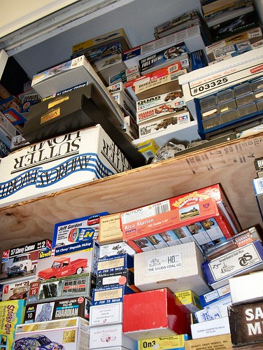
I thought it would be good for my morale to just crank something out as long as it was something I could complete within a weekend plus a week of evenings (about 8-10 hours total build time).
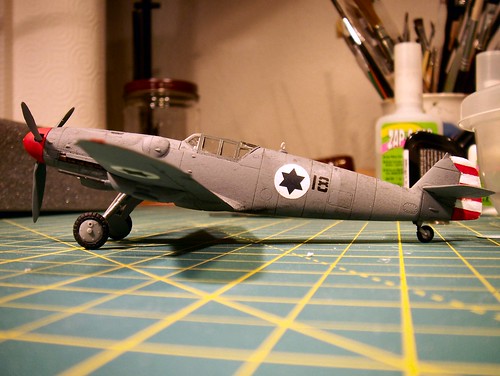
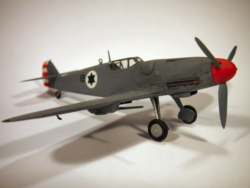
I chose a 1/72 scale Hasegawa kit of a Messerschmitt Bf109G-6 that I’ve had for years. I find myself incapable of building a kit straight from the box. I remember reading that the early Israeli Air Force flew ME-109s alongside Spitfires and Mustangs – often against Egyptian Spitfires. I had some Israeli A-4 Skyhawk decals I could use so I was all set.
If you’re a train modeler you may be asking “why is this a useful exercise?” I think the answer is that all model building projects contain common elements: research, construction, finishing, photography, self-critique. There are skills common to all successful miniature projects.
I was also trying to overcome a crisis in inertia and modeling motivation…
Research
A bit of digging showed that the plane the Israelis flew was not an ME-109 but an Avia S-199. These were produced after WWII by Czech builder Avia mating available ME-109 airframes with available Junkers Jumo-211 engines. The result was an inexpensive but unforgiving airplane that the Israelis used but retired as soon as they could.
References:
Wikipedia – Avia S-199
101 Squadron, Israel’s first fighter squadron
Rudy Augarten – avenging the Holocaust.
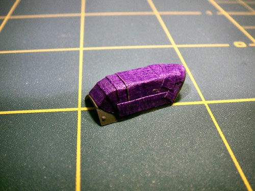
Construction
It was clear my model was going to be incorrect in numerous details but I was set on completing the model anyway. It had been so long since I’ve done an airplane model I had to look up the recommended construction sequence. The main trick is building enough to be ready to paint and decal the body without having too many small detail parts in your way. Fit was generally excellent for this model and I did only a minimum of seam filling and sanding work.
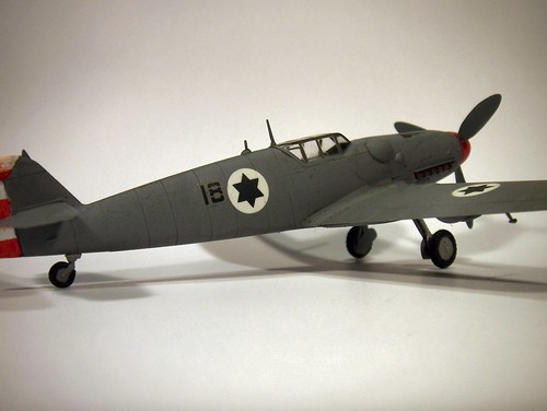
Finishing
I avoided using my airbrush since I do not currently have all the infrastructure in place to use it. I used a glossy gray spray paint and matching acrylic (Tamyia) paint to do the main finishing. I added decals to the glossy finish and sealed them with clear acrylic paint. The entire model was covered with a couple coats of matte finish and weathered with black acrylic paint diluted to a thin wash. This wash pooled into the panel lines and highlighted them nicely.
I installed the canopy fairly early but kept it covered with masking tape.
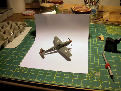
Photos
1/72 is a small scale in which to build a relatively small plane. The finished plane is only 5 inches long. For a model built for fun the main reason to take photographs (besides being able to share my work with the Internet) is to look for things I did right or wrong. Photos are harsh critics and see teeny details far better than my increasingly aging eyes!
Self-critique
Detail errors I don’t really care about: I want to get my list of errors in before I get flamed by the aerial equivalent of the rivet-counters.
The air scoop is on the wrong side of the plane for the Jumo engine. The shape of the nose near the prop is also wrong for the Jumo. The canopy on my model is the old “Galland” birdcage canopy whereas the Avias had a later model canopy with far fewer frame bars. The main wheel hubs are wrong and the markings are a fantasy I made up. I like what I built so this is really my list of “known issues that I’m not super worried about”
What do I wish I had done better?
The black wash worked great but the panel lines on the wing do not show as well as those on the fuselage.
The rudder stripes look like they were painted with a broom. I made the mistake of installing the horizontal stabilizers onto the tail before painting the stripes.
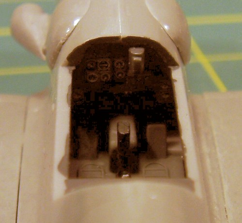
The cockpit is so dark inside it is impossible to see any details through the canopy.

With contrast enhancement:
The decal “18” on the left side shows air bubble “silvering”

The landing gear are not aligned right and this is after resetting them straighter three times!
Sun 18 Mar 2007
Posted by Daniel Swearingen under
Layout DesignComments Off
Planning how you’re going to build and clean those far corners is a challenge that I think you will always have with a diorama-style layout. The payback is deep immersive scenes that photograph well. I seriously considered fitting a shelf style layout into this space (see The Shelf layout plan – not for me) but decided it was not the kind of model building I was interested in.
John Applegate asks “how do you reach the corners?” in a comment on my post
Roughing up the town of Tiburbon
I was wondering if you have any “reach” issues with this layout. Are the right-hand & left-hand corners within 36″ reach limit? I noticed you placed the layout against the two walls thus disabling you ability to reach from behind. Any access hatches needed?
Reason I ask is that I am planning to do the SJC in Sn3. And in Sn3 I will have reach issues.
-John
Since my Northwestern Pacific layout is a walk-in style layout and not a shelf layout it is really hard to avoid having places that you can’t reach.
The quick answer is that from above, both corners are out of reach but I’m making them accessible from below or beside the layout.
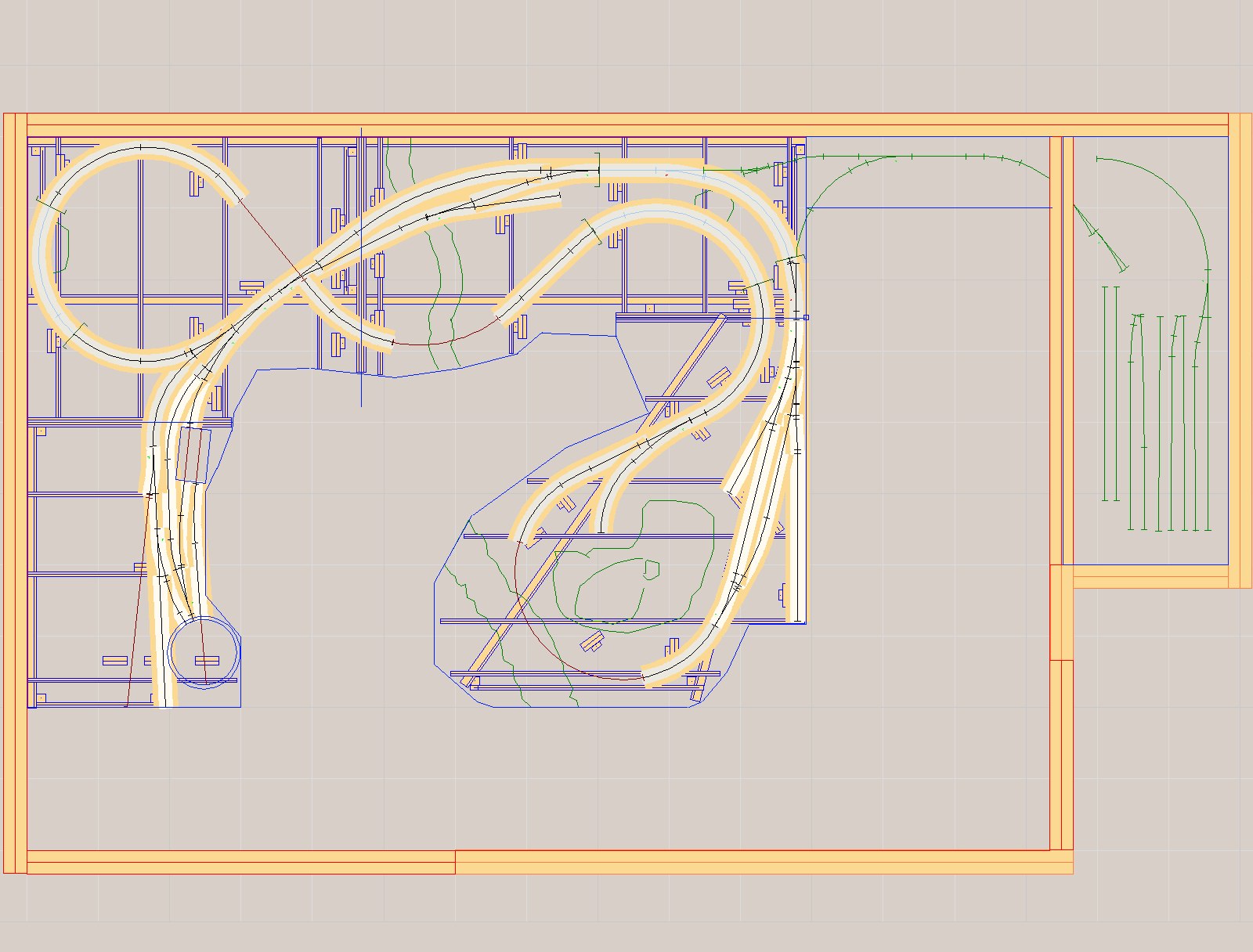
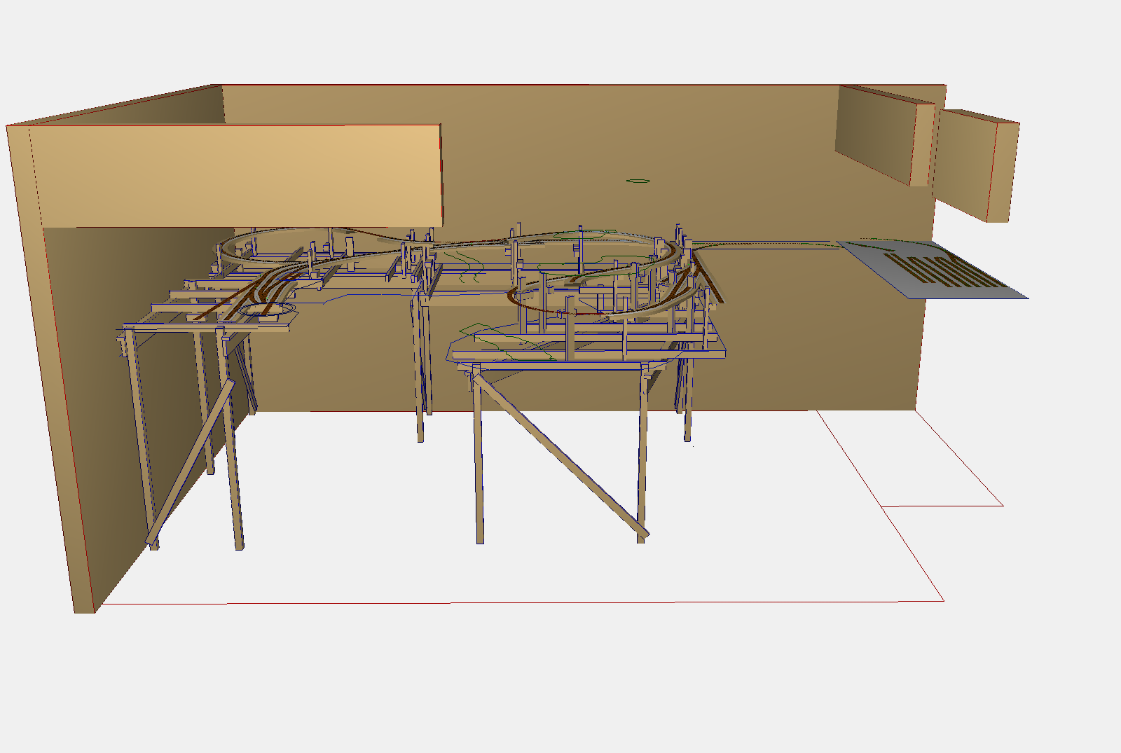
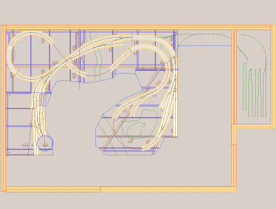
Here’s my track plan and room arrangement (from My Track Plan):

For the “left” corner I’m following Malcolm’s lead and leaving the back of the hillside open. From below I can almost stand up under the hill and service the loop of track in the back corner.
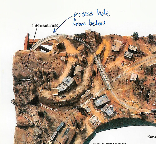
Note that the illustration above was made by mirror flipping and marking up a photo of the original San Juan Central layout so it matches the orientation of my layout.
For the right side I’m going to leave the side open (or have a removable fascia board) so I can reach in.
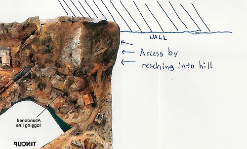
Note again that the illustration above was made by mirror flipping and marking up a photo of the original San Juan Central layout so it matches the orientation of my layout.
On a larger version like the Sn3 layout John is thinking of (or On30, On3, etc.) it would probably be a good idea to allow some access from beneath this area as well.