Track


Yes, I’m still futzing with the track and that darn hill. As I described last time, the hill was too steep and I lowered the end height ¾” and estimated that I had brought the grade down to 6%.

Was it really 6%? I decided to do what I should have done in the first place, really measure the grade. With a ruler and a level-bubble I was able to estimate the grade easily enough, but I could see that the hill was steeper in some places than others. I decided I needed better measurements to not just tell me the grade but tell me how much I should correct elevations along the grade to smooth things out.

Couldn’t I do this with the CAD system? Not really. Something 3rd PlanIt does not do well is vertical transitions and what I’m talking about here is an eight foot ribbon of plywood that eases up to the grade, climbs (and goes around an 18″ radius turn), and finally levels off at the top.

So I got out a ruler and measured the height of the roadbed every three inches to the nearest 1/16th of an inch, entered the measurements into a spreadsheet and found some trouble. The average grade was 5.8% — very close to and below the original estimate. However, that average was made up of sections at about 4% and others at 8%.

Making the speadsheet also made it easy to calculate which risers needed to be adjusted and by how much.

While I was at it I decided to try to pull off another ¾” from the overall climb. To reduce the need to climb I had to change the type of bridge from this:

to a plate girder type bridge like shown below which allows a minimum rail-head to rail-head distance. The bridge shown is a standard Atlas bridge which is not realistic if examined closely — I’ll have to take care with detailing and finishing.

And lose that beautiful Howe truss bridge? No, I’ll simply shorten the wood bridge and it will continue to the left.

 The good news is that the reduction in height reduces this grade to 4.5%. The climb up the other side of the hill becomes 3.7% (same climb but longer run). Now that (admittedly still steep) grade is even with no sudden steeper parts.

Lesson learned: measure, test, measure, and measure again.

The continuing saga of my learning curve building Central Valley Model Works turnout kits. In part one I did the basic assembly.

Now that I’ve added some track around my turnout I can actually run trains over it. The turnout works very well but I did not do a perfect job assembling it. I’m trying to be a very harsh critic of myself because several turnouts on the layout are in tough to reach places and I need to be very clear on proper technique before I build them.

Few things will ruin the enjoyment of your layout more than a turnout in the back corner that keeps derailing everything.

The main things I did wrong are not get the rails tightly enough around the frog and I did not snug the guard rails close enough to the stock rails.

Using an NMRA standards gauge you can see that the track gauge is correct but the width of the flangeway is not correct. For those not familiar with this tool the tabs highlighted in red show how wide the flangeway should be.

Given the way the frog casting works, snugging up the guard rail (the black plastic rail on the left) will be the easy fix.

One thing to watch is to make sure that the frog rails (the rails that are attached in a “V”) are pushed as far forward into the frog casting as possible. However, this can be taken too far since the geometry is such that if pushed too far forward the track gauge will become too narrow.

An easy fix: make sure the closure rails (by the arrow on the right)

are really tight to the frog casting. Note that the closure rail on the left of the frog (to the left of the RIGHT arrow) is loose. The closure rail on the right of the frog is pretty good.

Despite these obvious flaws the turnout works flawlessly (if a bit bumpy for some pieces of rolling stock) so I have to admit that the Central Valley design seems to be quite forgiving.

So I finally got some track laid up hill from my first turnout. Where have I been? My day job is building a piece of Microsoft’s latest operating system and we had a BIG deadline…

Anyhoo, as soon as I had two whole pieces of flex track down I did what every red-blooded model railroader does: hooked up a power pack and ran some trains!!

The good news: the track is nice and smooth and the one turnout works flawlessly despite obvious imperfections (see other post).

Too Steep

The bad news: I had been worried about the grade uphill from the turnout. On the plan it works out to about 5.8% but that’s with no vertical transitions. With the transitions (effectively the distance it takes for 1/2″ plywood to smoothly bend to the grade) the same height is being gained in less distance — so the real hill is steeper.

Honestly, I knew all this going in, but I had not measured the grade. When I ran a train I found that my thumping Life-Like USRA 0-8-0 swticher could not pull even two free-rolling Athearn 75’ shorty passenger cars up the grade (not that I ever plan on using those cars on my 1920′s layout but they were handy…). Oops. The grade is more like 7%-plus!

I had to lower the grade. Looking at the layout, the height of the grade had been determined by the height needed to clear over the return loop with clearance. I had arbitrarily chosen a pretty high clearance at that point.

However, I needed to reduce the height climbed as much as possible so I made a template based on the Howe truss bridge that will be used at that point and measured how much I could bring the upper track down while still clearing the NMRA recommended height.

I was able to reduce the height by 3/4 of an inch. That may not seem like much but the total climb was 5″ so that’s a 15% reduction. With the reduced grade comes a reduction in the needed vertical transitions so this brings the grade down to more like 6%. Still severe but more workable — and more like what I had planned.

How do you lower twelve feet of roadbed? Unscrew the risers, clamp at the new (lower) height, and re-screw them. Not too pretty but nobody will see this once the scenery is up.

Note that RAISING the track would be MUCH more work.

Can the 0-8-0 get the two cars up the grade now? BARELY. Luckily, my designed train length is four 40′ cars plus a caboose and the prototype NWP often needed doubling on their frequent short-steep hills.

As I left off last time I had decided to buy a Walthers 90’ turntable instead of scratchbuilding.

Placing it into the rough cut 11” hole I had already cut, it was clearly going to need a bigger (and more perfectly circular!) hole.

The Walther’s turntable needs a 12-1/2” diameter hole. On my trackplan I superimposed that size hole where I had the smaller hole and it was a tight fit, but it did fit.

It is a good idea to read the instructions: closer reading reveals that the turntable needs a 12-5/8” hole. As usual – everything ends up taking a bit more space than you initially plan.


First I needed to draw a really accurate circle on the plywood. Normally this is no big deal but there’s a hole in the plywood where the center needs to be so I clamp a piece of ¼” plywood over the hole from below.

Next I need to mark the center of the circle. The approach tracks to the turntable are already laid out and their centerlines should cross exactly at the center of the circle. Using a flexible clear plastic ruler I draw lines out and where they cross will be the center of the new enlarged hole.

Drawing the first line.

Drawing the second line. Where it crosses the first is the center for the new hole.

From the center just marked I use an inexpensive compass and a sharp pencil set for a 6-5/16” radius to gently mark out the new circle’s outline. This kind of compass works fine as long as you use very little force.

Drill a starter hole for the saber saw.

Cut the hole

Somehow I forgot to take any photos of this step. Maybe it was because I was holding the saw with both hands!

Anyway, I carefully cut the hole with a new blade in the saber saw and with a little bit of shaving the new hole works great.

The edge of my plywood base for the yard area is now dangerously close to the edge of the turntable so I immediately add some pine 1×3 facing boards and use a cargo strap to hold them while I glue and screw them in place.

The plastic lip of the turntable is exactly the same thickness as the ties under my track. Since my track is riding on cork roadbed I need to raise the turntable to match the track height. The easy way to do this is to run a ring of roadbed around the turntable hole to use it as a riser. Then I just cut away the bevel where the approach tracks come in.


I still have to actually assemble the turntable but I’m moving on to laying the track first.

Ok, so far this first turnout is kicking my ass. I’ll produce a real “how to build these turnouts” article — when I really know to build one of these turnouts. Right now, I’m severely learning. Think of this as a “still clinging to the cliff” kind of report although I’m still having fun and I’m still happy about choosing the Central Valley turnout kits.

Central Valley Model Works (CVMW) has been around since the late 1940’s. However, their CVT system of styrene tie strips and turnout kits is relatively new. I’m building most of my track using Micro Engineering code 83 flex track. Code 83 you say? Yes, I have some old Rivarrosi and IHC engines that I actually like, and code 70 is too low for their (way too big) flanges so code 83 it is – good enough.

For turnouts I originally intended to use Walthers/Shinohara code 83 #4’s – these are excellent turnouts but were completely out of stock for the foreseeable future during the end of 2005 when I was putting all my materials together. I procrastinate enough at the best of times and having any real excuse to stop forward progress is simply too risky so I shopped around for an immediately available alternative. The CVT turnouts had been on my short list and they were available. I ordered straight from CVMW and they arrived quickly.

The pros, cons, and costs of the CVT turnouts are obvious:

Pro: great detail – museum quality looks.
Con: you need to build them yourself and I feel it’s fair to say that they are one notch more difficult than the normal way one would scratch build a turnout and obviously way more work than a pre-built turnout.
Cost: very comparable with other turnouts. Not really a factor in the decision.

I picked a spot on my layout to lay the first turnout.

An easily accessible simple siding on the mainline. The CVT instructions (yes, I actually read them) say to start by gluing down the tie strip onto the layout. However since this was my first one I chose to do a quite a bit of dry fitting on the workbench before doing anything on the layout.

I made a drilling template out of ¼ masonite and drilled the “throw” hole and holes for feeder wires. Then glued the tie block down with contact cement and glued down a small piece of roadbed to be the foundation for the switch stand.

I’d love to say “then I just attached the rails and away we go” but there has been a lot of learning. Central Valley recommends barge cement diluted with MEK to attach the rails. I tried it and this is a really good recommendation — but there is still some art involved.

After some work I got my first turnout installed and working.

I’m using Tortoise switch machines and I’m using 1/16” square brass rod to throw the turnout.

Yes, actual construction! I’m breaking from the ranks of arm-chair modelers where I have been comfortably hiding (and yet still whining) for many years.

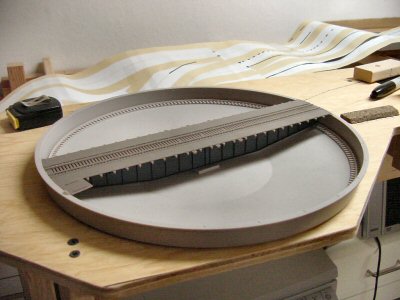
As soon as I finalized my trackplan I built a planning model to confirm I liked the track alignment and arrangement. Now I was ready to start actually building benchwork.

One of the benefits of using a CAD system like 3rd PlanIt to design your layout is that it gives you a list of which materials needed and how much of each. Exporting this data I had:

L Girder, 1×4 = 489
Wood, 1×2 = 1635
Wood, 2×2 = 843

Where these last numbers are amount needed in inches. Converting to feet and then figuring out how many 8, 10, or 12 foot pieces I needed, I was able to make one trip to the lumber yard. Okay, one and a half trips because I oops’d at one point and did not leave myself enough long pieces so I had to run back and buy a couple extra 1x4’s.

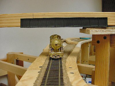
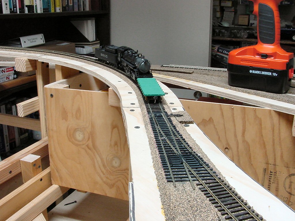
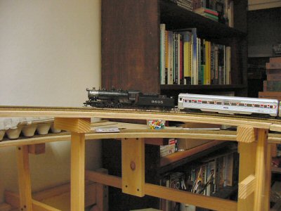
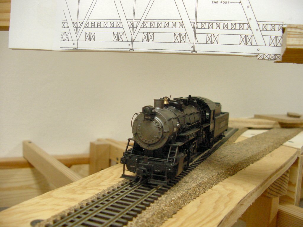
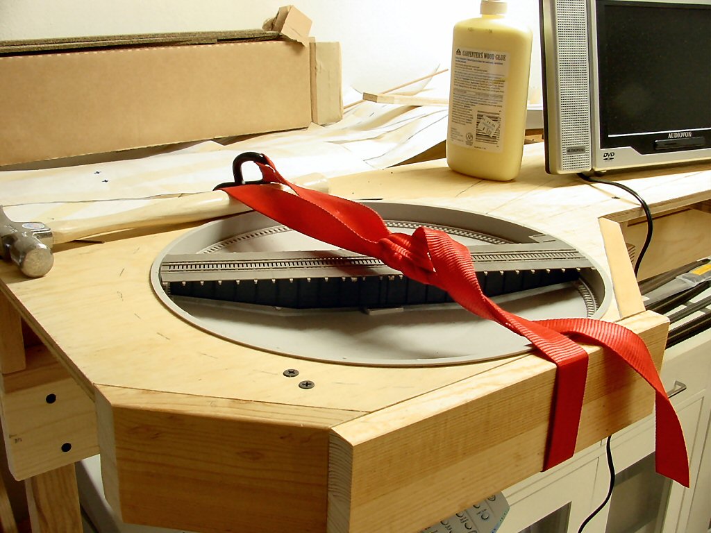
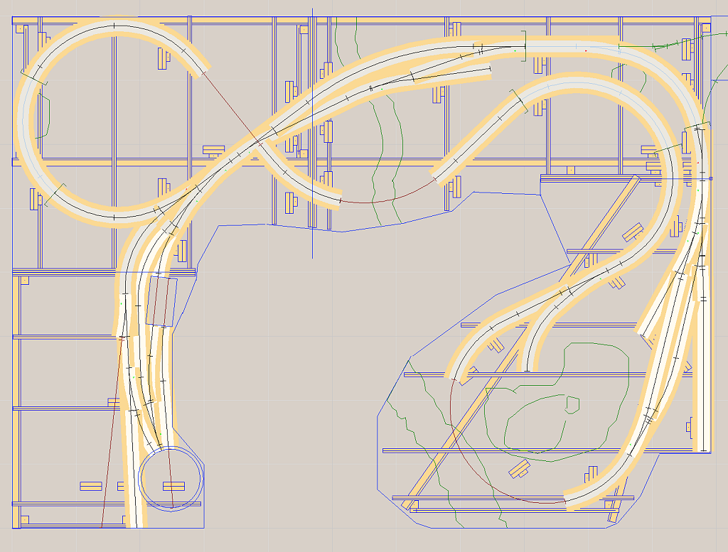
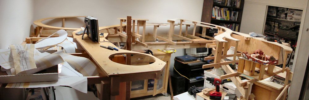
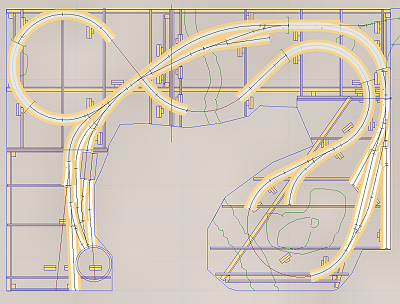
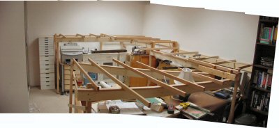
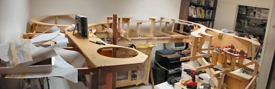
Benchwork with track.

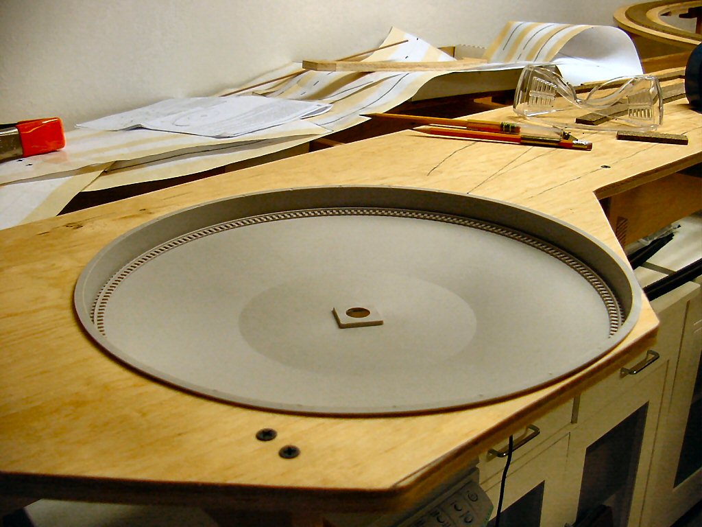
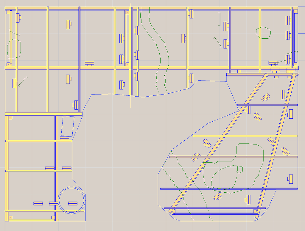
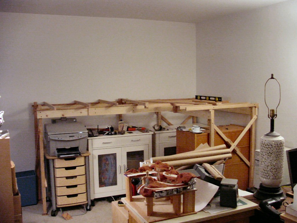
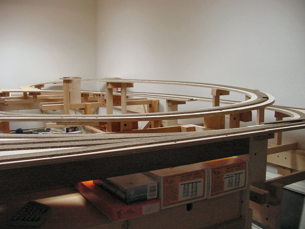
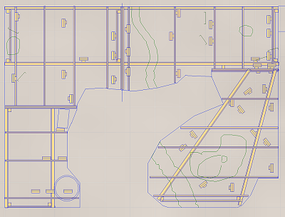
Benchwork without roadbed and track.

I’m building the layout into four big pieces. This is part of my plan to make the layout movable (but not necessarily easily portable).

It is important to get the first piece lined up well because it is much faster and easier going forward if you can just use the first section as your solid reference. Another decision I made was to build only the first section as a free-standing four legged section. All the other sections would have one end held up by its neighbor and the other end held up by its own legs. This minimized the number of legs needed and increased the amount of clear space below.

I built up the L-girders and cut all the legs and joists to length outdoors in advance, measuring from the CAD drawings.

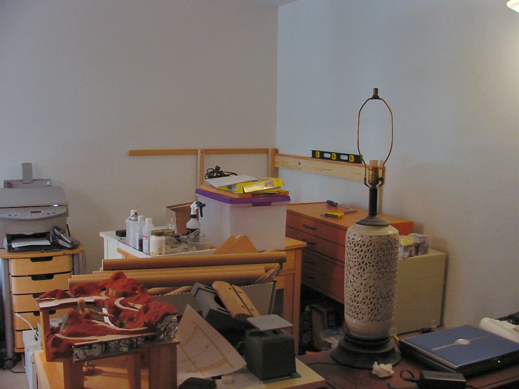
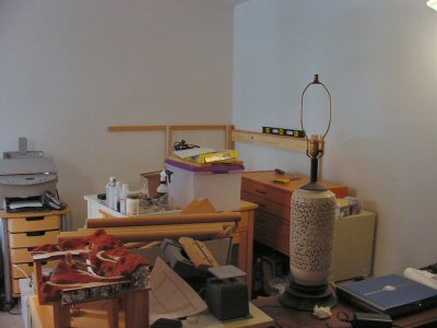
Believe it or not, I live in an apartment. Let that sink in a second. An apartment. Not only do I live in an apartment, but my wife and I are spectacular pack rats. We have STUFF. My son has stuff too.

Therefore, one thing you will see in these pictures is that I could not actually start with an empty room. There was nowhere to put the stuff. An important factor in my design was that as I build a section, I move stuff under that section, clearing space to build the next section. That under-layout storage is important and was another motivation to have a rather high 53.5 inch track-zero height. I did have to fill the hallway and the living room with some displaced stuff over the one month it took to build the benchwork.

My son thought the whole thing was great. And yes, my wife is a saint.

Here’s the first section going up.

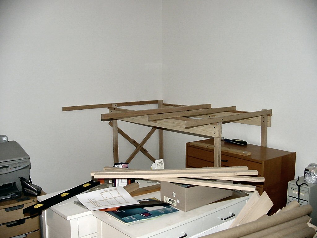
Once the first section was up it’s ready to hold up the next. I put ¼ inch lag screws on the ends of all the legs to allow the height to be adjustable for any irregularities in the floor.

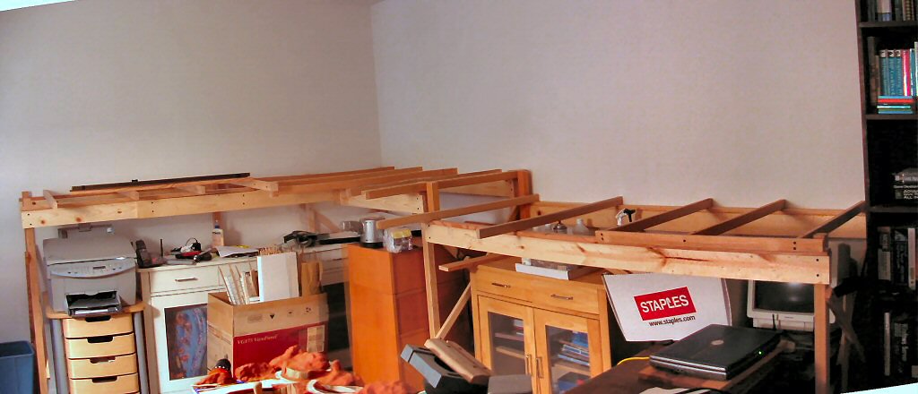
Here’s the next section and as you can see I’ve already snuggled a bunch of stuff underneath. Note everything is on wheels so it’s pretty easy to pull stuff out if I need to get underneath.

Continuing on with the third section. The sections are attached to each other only along facing 1×2 face plates at the section edges.

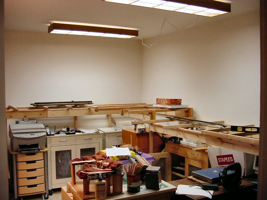
It finally dawned on me that I need more light in this already effectively windowless room. I bought a couple fixtures and put decent (relatively expensive) “full spectrum” tubes in them. I’m surface mounting everything since it all has to come out some day. I’ve tidied up the cords much better since this photo.


Note: this is just a start on the light. Fluorescents are an efficient way to get the bulk of the light into the space. I plan on adding many small halogen spots to give good shadows and a warmer color.

Last section.

In several of these last shots you can see that I’m using an image stitching program to combine shots giving a wider-angle view.

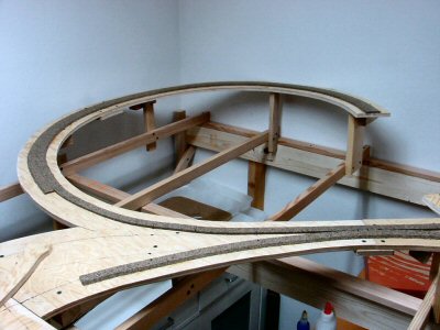
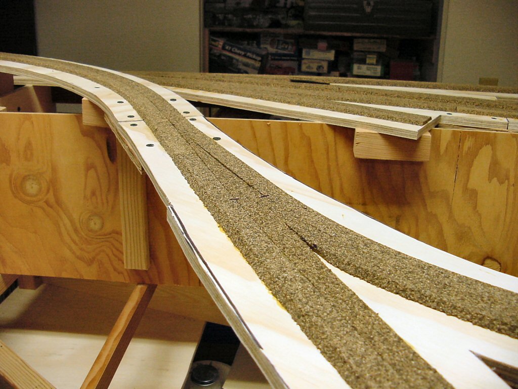
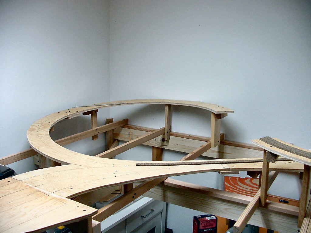
Roadway – note I use the term “roadway” to refer to the wood structure beneath the roadbed where “roadbed” is the stuff you actually put track DIRECTLY on. Some people say “sub-roadbed” — I use ½” plywood.

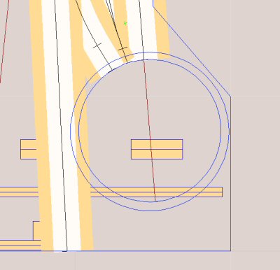
Building the roadway is one of those things that is REALLY hard without two things: the CAD system printing out full size paper templates and a saber saw. As far as I’m concerned there’s no other way to do it.

I actually made a paper model of the pieces of roadway to estimate how many sheets of plywood I’d need (three 4’ x 4’ sheets). By the by, unless you need several REALLY long runs, having the lumber yard cut 4×8 sheets of plywood into 4×4 sheets makes your life MUCH easier.

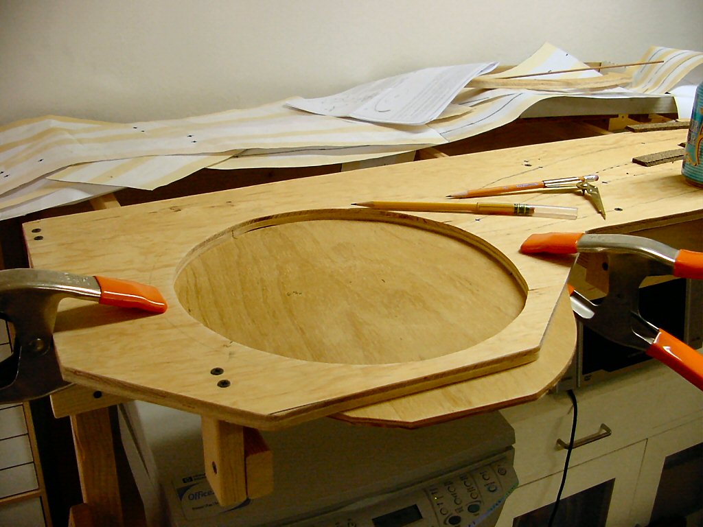
Anyhow, I printed out the full size templates from the CAD system (lovingly assembled from many 8-1/2 x 11 sheets of paper) and staple them to the plywood. I just staple them on long enough to copy their outline onto the wood using a nice new black sharpie pen. You can use a pencil if you want but the thick black ink line is easier to follow while cutting.

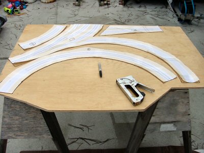
SAVE the templates: you will use them again later.

I don’t have any photos of actually cutting the plywood. It was threatening rain that weekend so I was hustling along fast enough to get it done yet still keep all my fingers. Besides the saber saw I also use a band saw whenever the shape of the piece is such that it fits through the throat of the saw.

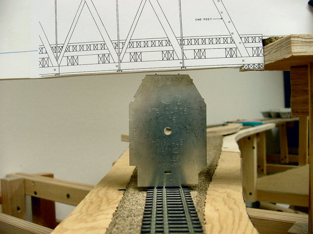
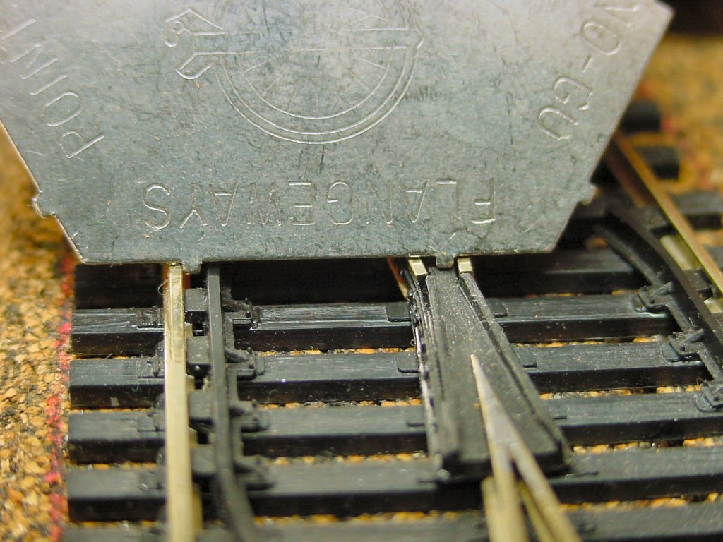
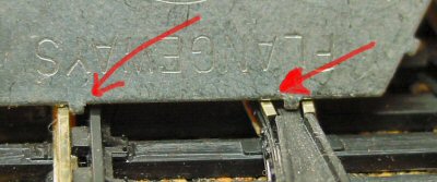
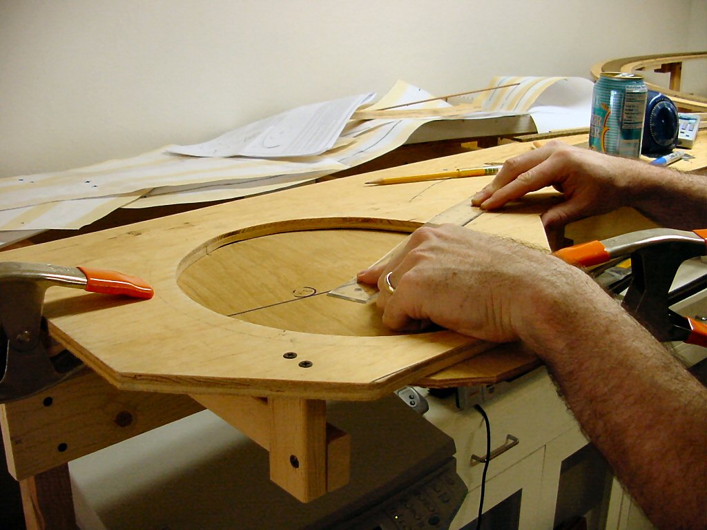
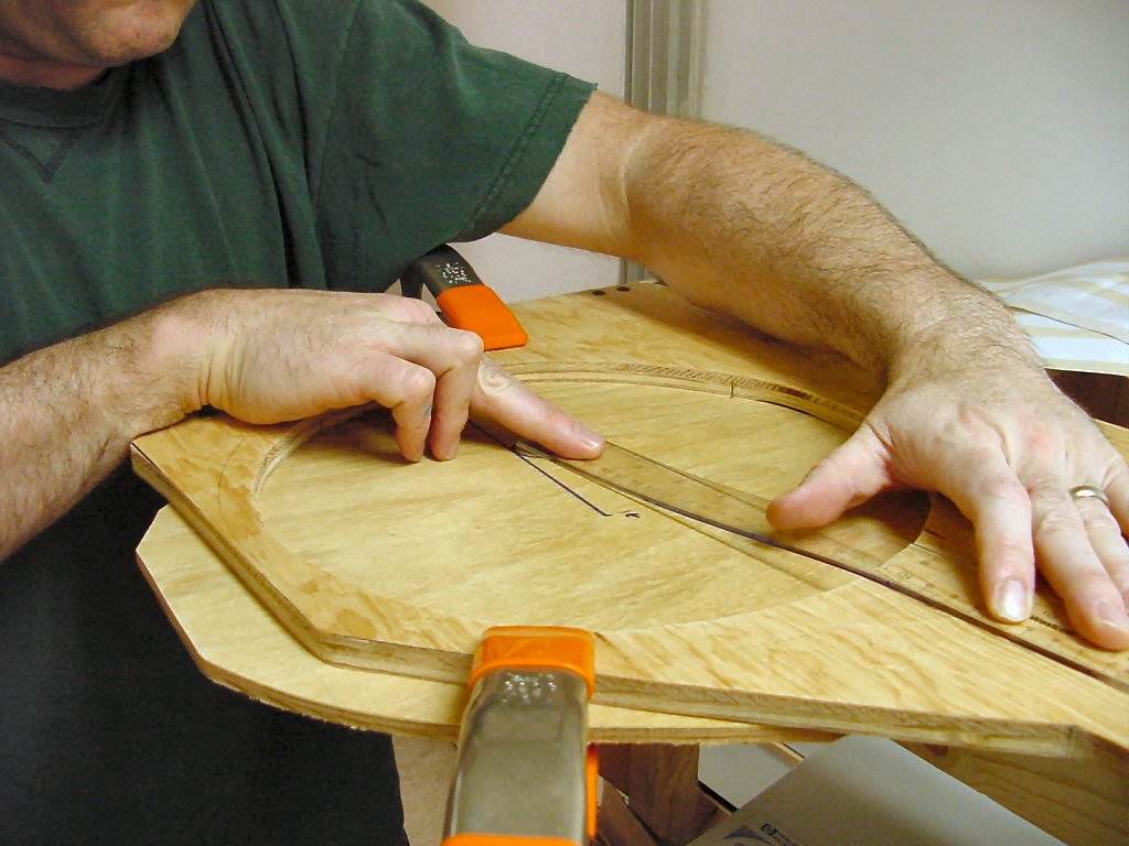
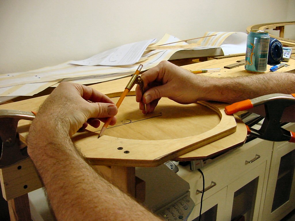
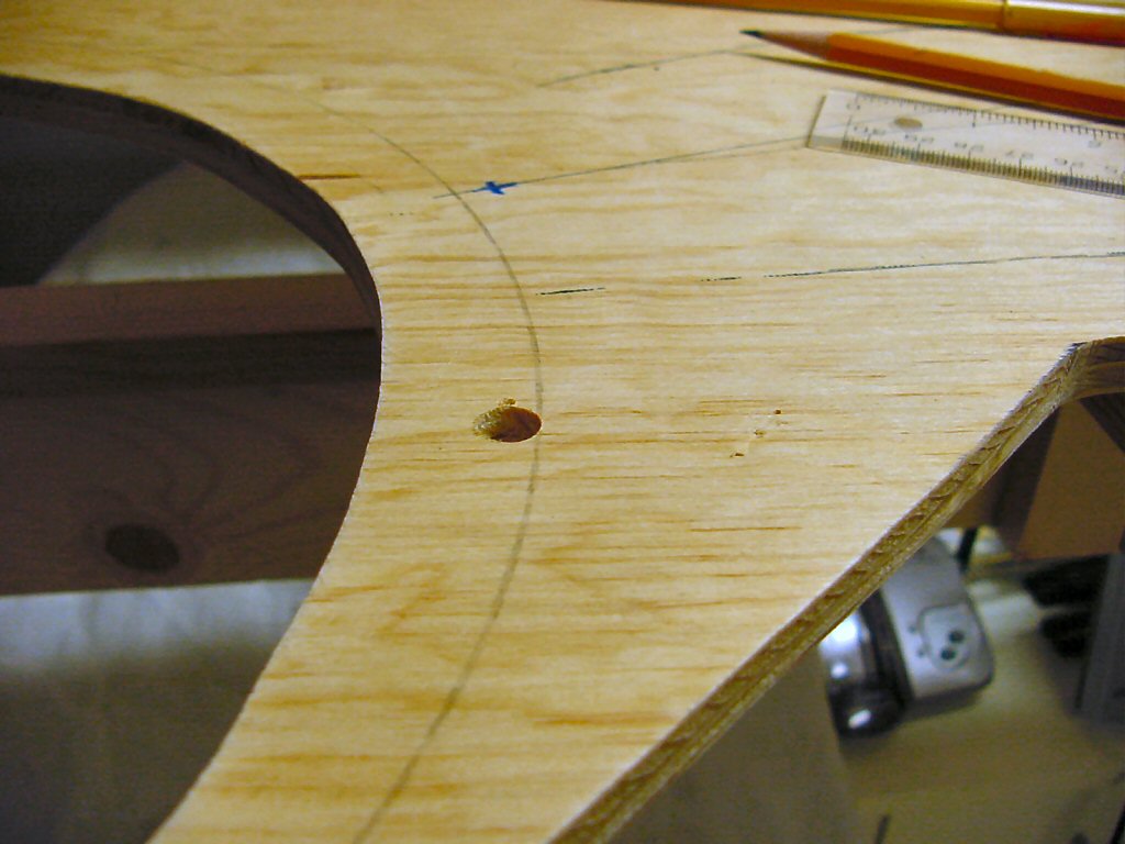
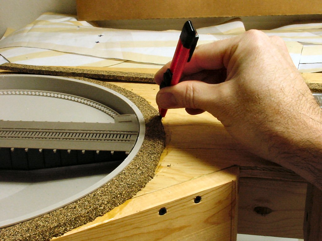
Remember I said keep the templates? You need them to quickly and easily lay out the turnouts and the track locations. Once the roadway was installed, I would tack the templates over the pieces and use one of my trusty sharpies to trace slowly over the track plan, letting the ink soak through and mark the wood.

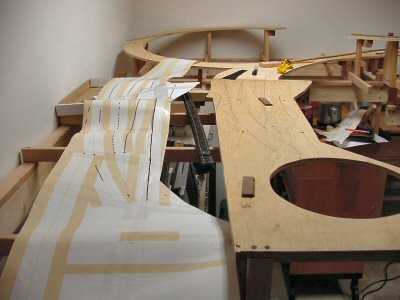
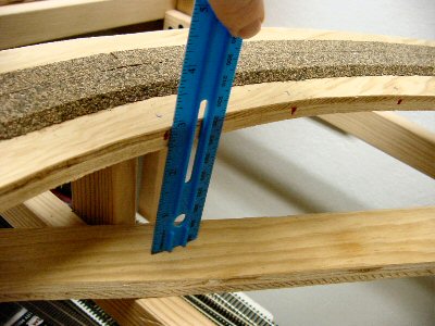
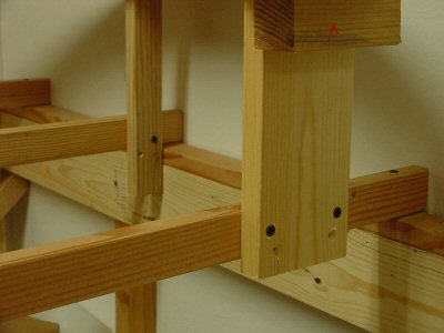
I was moving fast and the benchwork is definitely good enough but one thing I would change next time: Malcolm used 1×2 risers on his San Juan Central so I figured I would too. Next time: use 1×4 risers. The 1x2’s are plenty strong but because the 2 inches is so narrow (really 1-1/2 inches) they tend to be wobbly. For a small weight penalty, 1x4’s would have been much better.
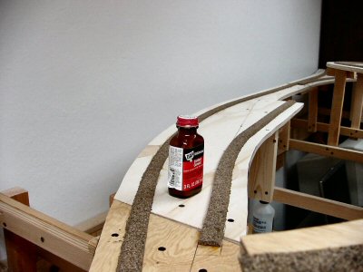
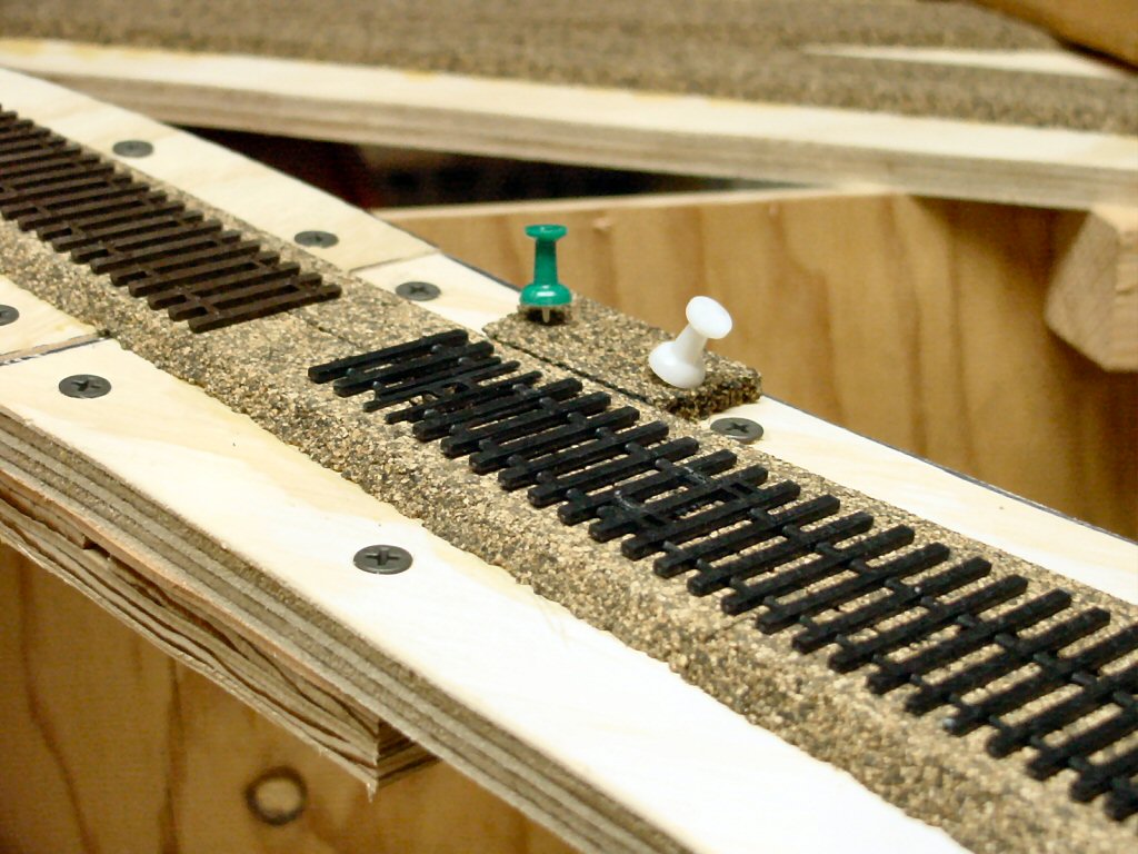
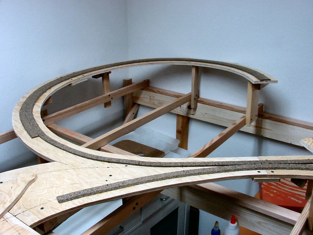
Cork Roadbed

It’s fast, relatively cheap, not too messy, and it’s good enough. If I was hand laying track I might have gone for Homasote but I just didn’t want to do it that way. Frankly, the old Tru-scale milled pine roadbed was pretty good. Now available from Trout Creek Engineering — the flat stuff you put your own ties on, not the stuff they made with ties and grooves cut into it. I’d probably do something like that before Homasote. Call me weird. The only thing halfway interesting about putting down the cork is that I would use contact cement alternatively with white glue to hold it down.

WOW. This is a gorgeous and effective tool.

I saw a blurb about Fast Tracks products in Model Railroader and thought I’d take a look. I’m using Central Valley Model Works CVT Turnouts which require a lot of hand assembly and you have to file rails to shape for the frogs. I was worried about this so I was looking for something to make good repeatable frog rails.

Fast Tracks makes a complete line of track building and especially turnout building tools for hand laid track. I thought the PointForm Filing Jig looked good and the website has a video of how it is used. That is very cool and sold me. They are a small operation and sometimes get swamped with orders. In my case my order arrived in about three weeks.

The fit and finish of the tools are fantastic and they work perfectly the first time. Highly recommended.

I also bought their Rail Roller and I’ll describe that soon in another post.