Scenery


Easy Rock Casting and Coloring DVD by Darryl Huffman

Darryl Huffman's DVD

How did you do those rocks?
.

This was Darryl’s topic sentence for this how-to video. This looked perfect for me since the point I’m at on my layout is how am I going to do all those rocks!? 

I’m building an HO standard gauge version of Crazy Horse Canyon from Malcolm Furlow’s San Juan Central on my layout. I’ve got the shape of the scenery roughed out in Styrofoam but I’m stuck on the step of actually building whole area up with rock castings.

The questions I needed help with were things like: How do you handle the seams between castings to cover large areas? How do you color everything?

Darryl is a regular contributor to several of the model railroading Yahoo! groups and I have seen many photos of his work from there and his contest entries at the Narrow Gauge conventions.  Below is a structure he built and entered in the modeling contest at the 2004 Narrow Gauge Convention.


I ordered the DVD directly from Darryl on his website and it arrived within a few days.

The 70 minute video is divided up into five chapters about making, blending, and coloring rock castings plus one neat extra chapter about how to use colored crushed plaster to make talus slopes and bunches of rocks and gravel.

Even though I’m using casting foam instead of plaster for my rocks, almost everything Darryl demonstrates easily translates into that material.

Darryl’s DVD does a great job at making the process feel approachable and yields great results. At $20 plus $5 shipping I think it’s a great value too.

Order direct from Darryl at his website http://www.darrylhuffman.50megs.com/custom.html


This is taking longer than I would like. I’ll talk about this more later but I’m now seeing that building up a layout out of foam may be a good technique but quite time consuming. 

I’m staring to think that building up out of foam has its place but not as the way to build your entire layout.

One area it makes sense is around Crazy Horse Canyon since I have a pretty detailed idea how the terrain will be contoured and it will be nearly all rock castings.

First, I really don’t think building up layer cake style works as well as making vertical slices. I see in the December 2006 Model Railroader that Pelle Søeborg also builds this way.

I started by drawing pencil lines on my planning model that I would turn into profile cut pieces of Styrofoam. Next I used a profile gauge to transfer the profile onto a scaled piece of graph paper that matches a 2” square grid.

Then I marked my 2” thick 2 ‘ x 4’ pieces of Styrofoam with a 2” grid.

Transfer the contour to the big board.

Cut with either a hot-wire cutter or my hot knife. If I can reach far enough I use the wire cutter since it does finer work but if not I use my hot knife which can reach anywhere. Then I place the piece in place.

The “back” side of the hill behind the canyon I measured by pressing the contour gauge straight down.

The “front” side of the canyon is mostly vertical and even has an overhang

so I pulled off the bit of modeling clay opposite the cliff and measured it by pressing the contour gauge straight into the cliff face.

As I add the pieces I place them unglued in position and then go back with a hot wire cutter and trim each piece to more nearly fair into its neighboring slice.

This makes a big mess even when you use hot cutting (although nothing like the mess you make sawing bead-board):

I figure nearly half of the styrofoam you buy ends up as unusable small scraps you have to throw away.

So far I’ve framed the canyon area and made a rough design plan for the bridge. Now I’m starting to rough in the scenery.

First I put down a couple pieces of foam core board to be the riverbed and sketched out outlines of the shore.

Then I cut some 2-inch bead board to fit these lines and the outline of the bench work (I’m going to need to start thinking about fascia material soon!).  I use a hot knife and a hot wire cutter to do all my cutting.

Once I had these flat pieces secured I cut some profile pieces to establish the high points.

Now I need to get some rock castings going.

No, the title is not a typo…

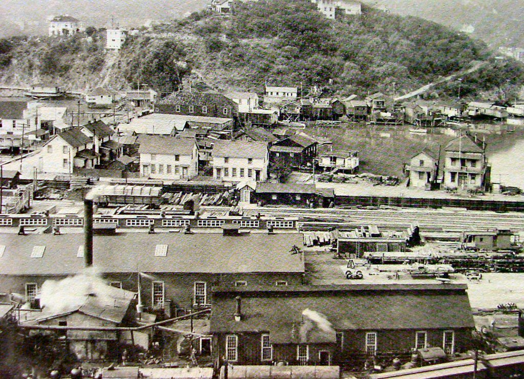
I’ve always loved photos of early Tiburon, California. Tiburon grew as the “town at the end of the tracks.” Those tracks belonged to the San Francisco & North Pacific Railroad and later the Northwestern Pacific Railroad.


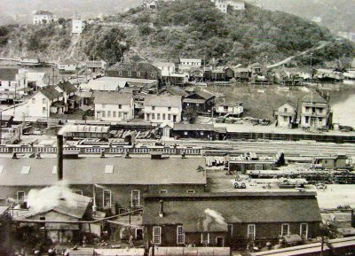
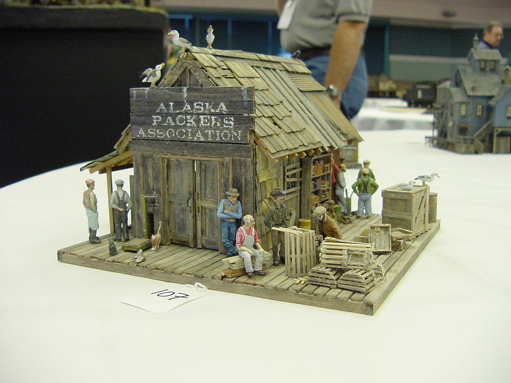
By the 1920’s Tiburon housed a dense cluster of rail yards, ferry piers, and shops. It was also home to an extremely wild bunch of buildings that grew organically around the end of tracks.

Because the shore near Tiburon was extremely steep, any flat ground was created entirely by filling in the surrounding bay. The railroad did a pretty organized job of it. The townspeople just threw dirt in as needed, drove piles into the remaining shallow water and threw up their structures in a way that would strike terror into the heart of any modern building inspector, fire marshal, or health inspector. Here could be found hotels, cheap housing for railroad workers, bars, cathouses, and stores.

The picture above is looking west. If you looked to the east of the yards and shops you would find much more respectable (but to me less interesting) housing.

I want a town on my layout that captures some of the feel and spirit of Tiburon of this era. However, given my tiny amount of available space I cannot make a serious attempt to model anything about Tiburon of the 1920’s except its “feel.” Additionally I’m going to emphasize, to the point of exaggeration, many of the more colorful aspects of the town so I decided to highlight that by dubbing my version of the town “TiburBon.” Amazing what the simple addition of a “b” does.

Locals insist Tiburbon is pronounced “Tiburr-bon” although visitors seeking a bottle of liquor (found here in abundance despite Prohibition) unfailingly pronounce it “Ti-bourbon.

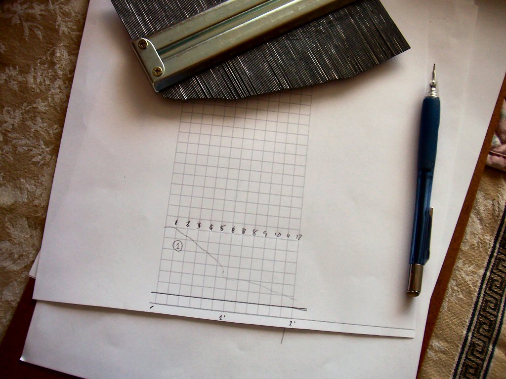
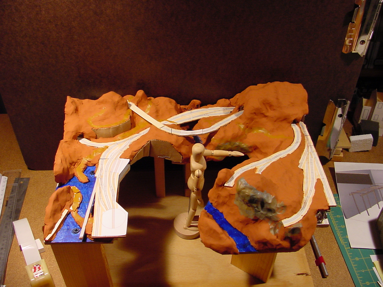
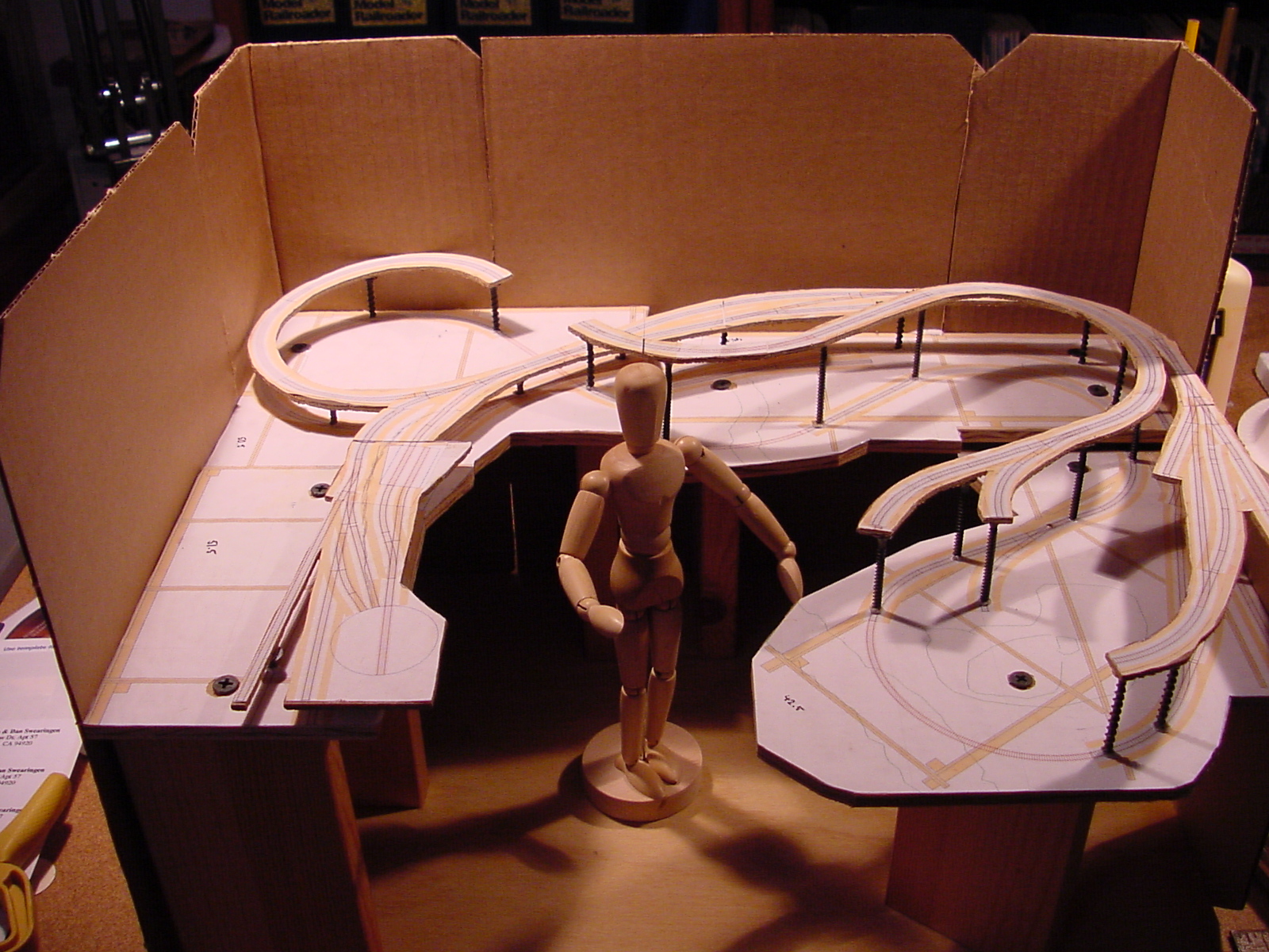
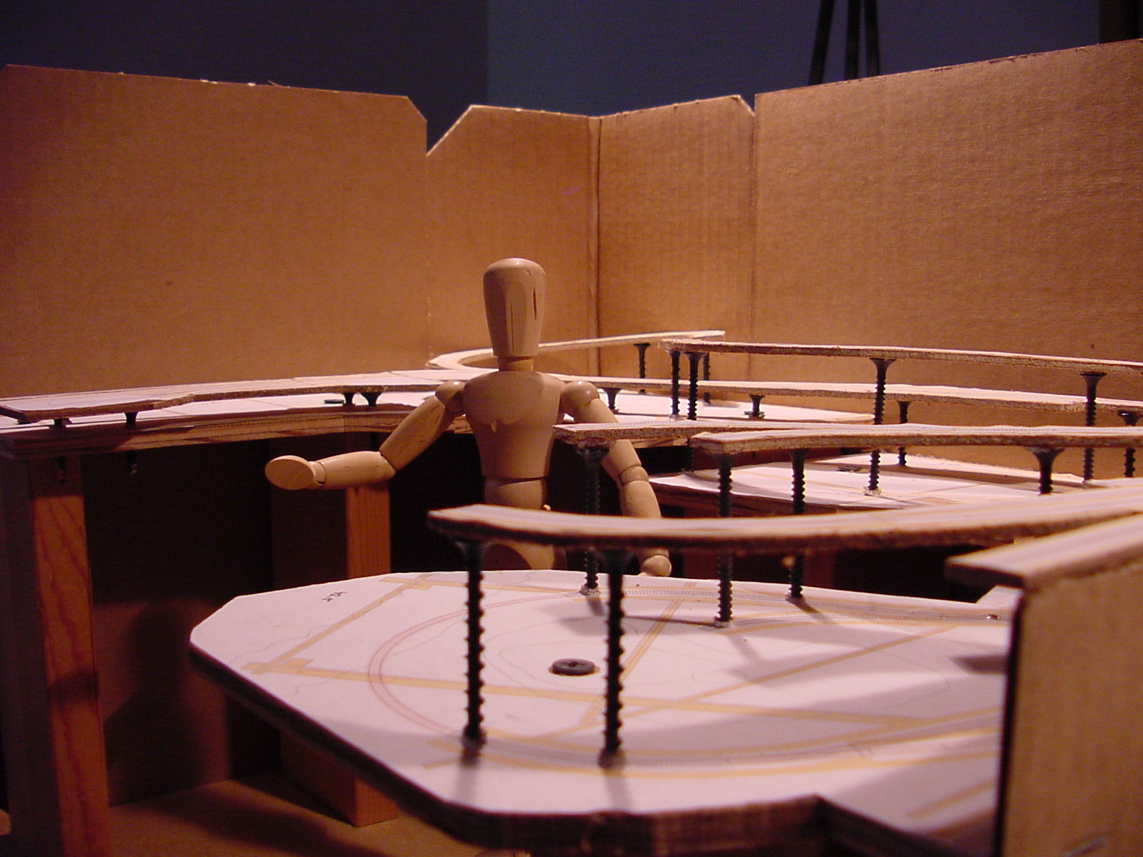
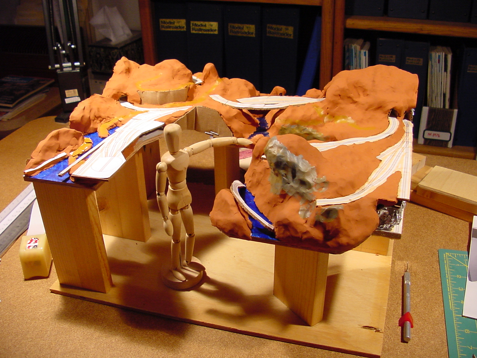
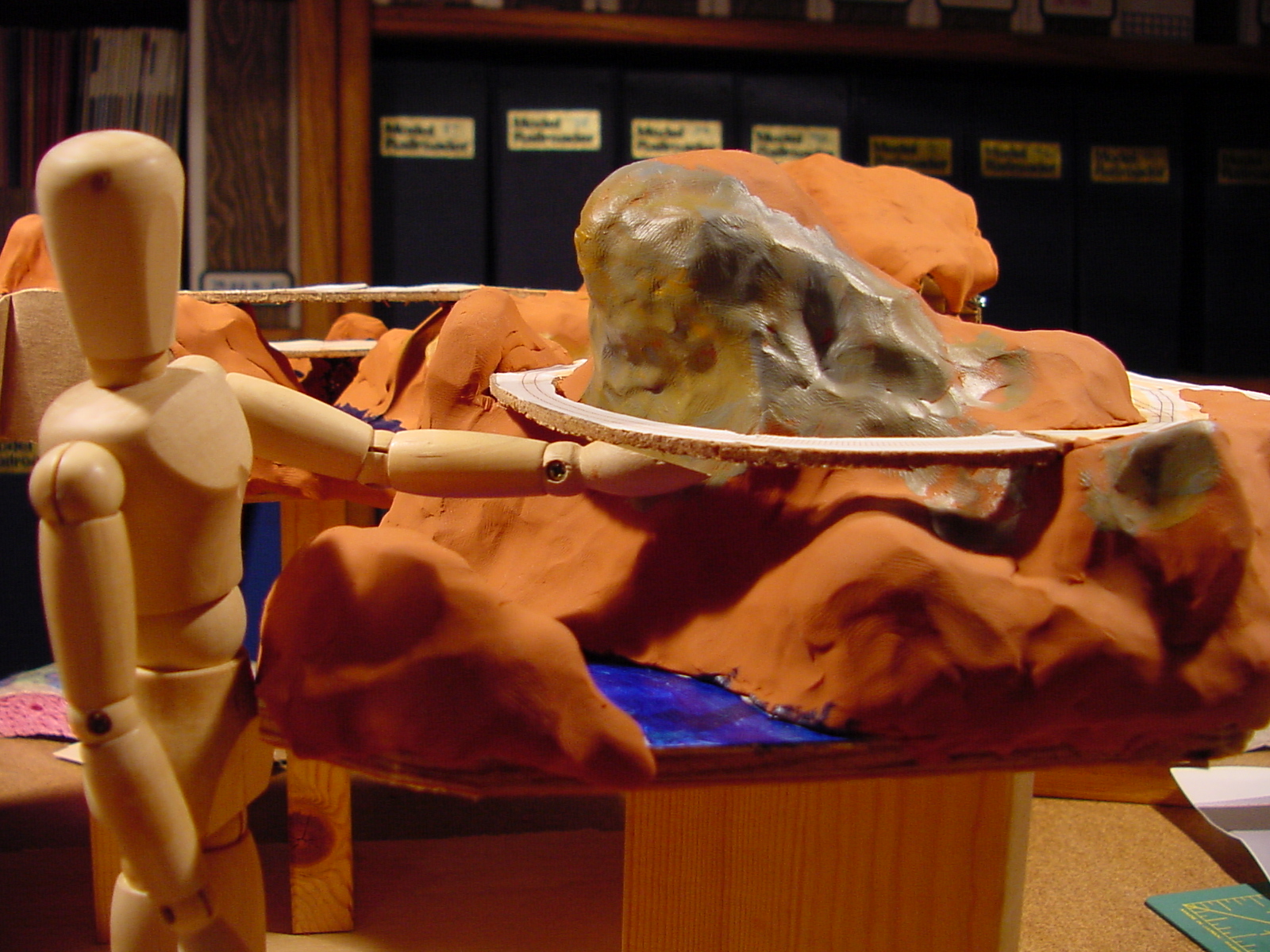
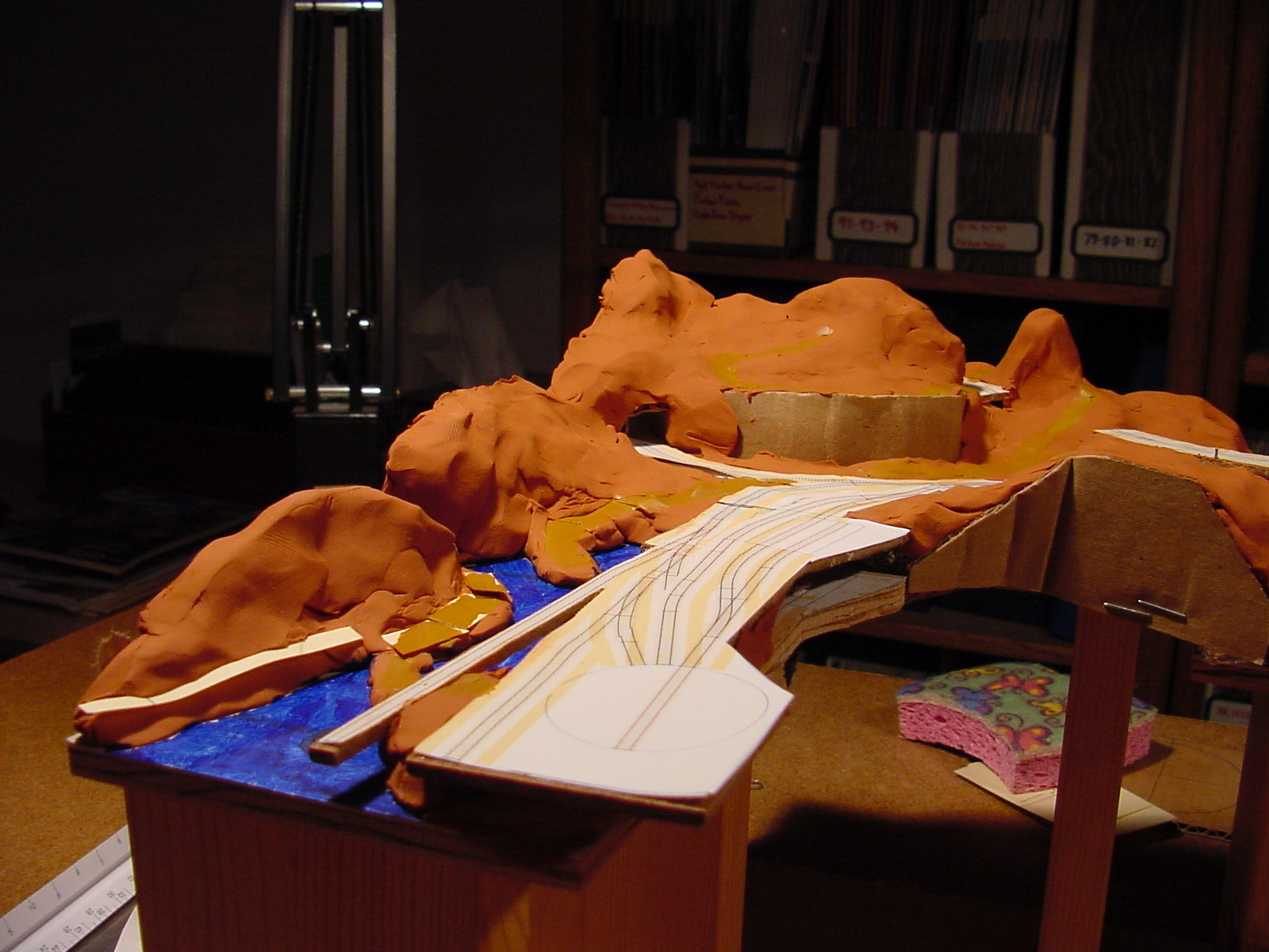
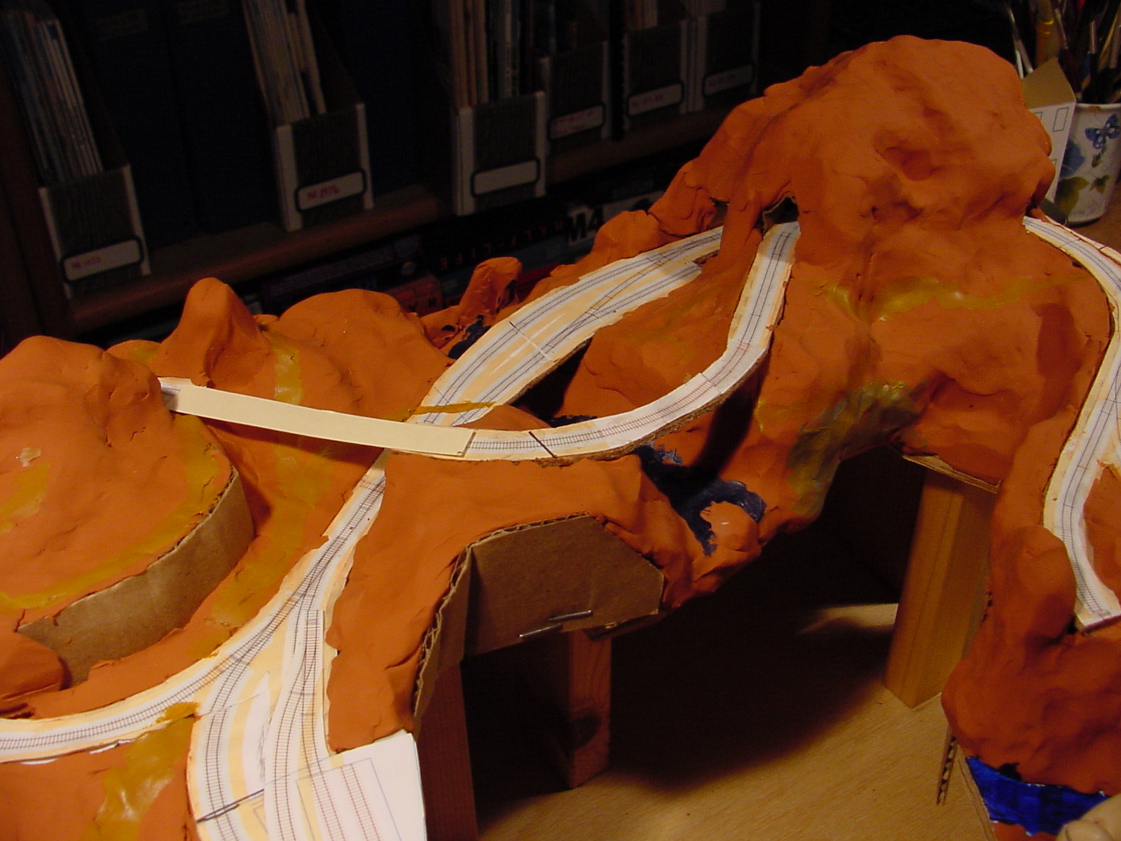
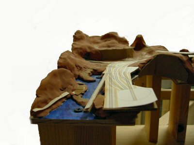
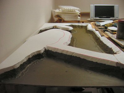
After looking at maps and photos of Tiburon in the past and walking the streets today (I live in Tiburon) I shaped an idea for the land and water around Tiburbon onto my planning model.


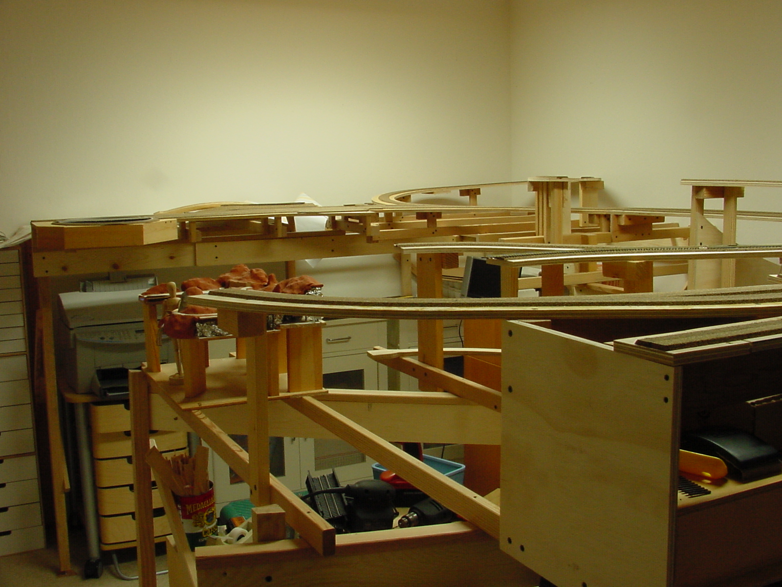
Before I go further with the track work in Tiburbon I decided I’d get a start on the rough scenery here since the town will end up a highly detailed scene behind the tracks and will be easier to work on before the track is laid in.


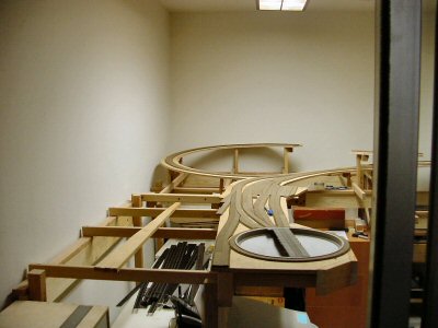
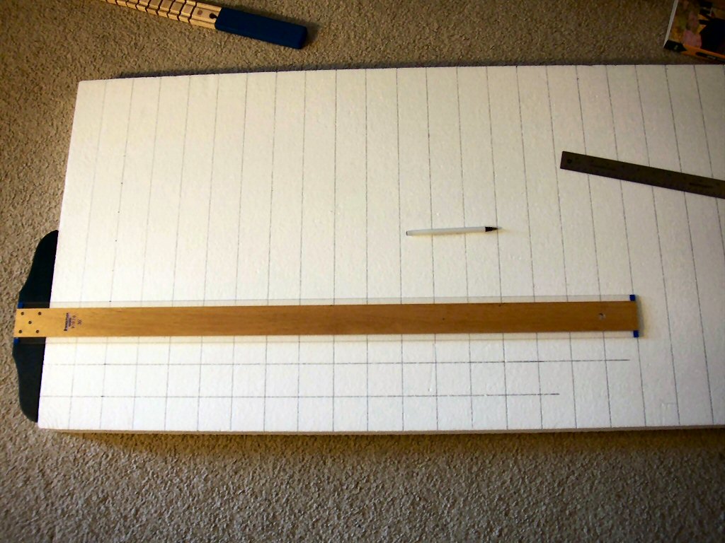
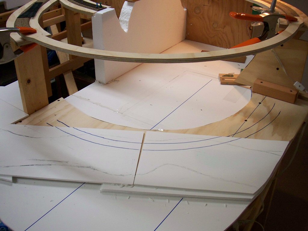
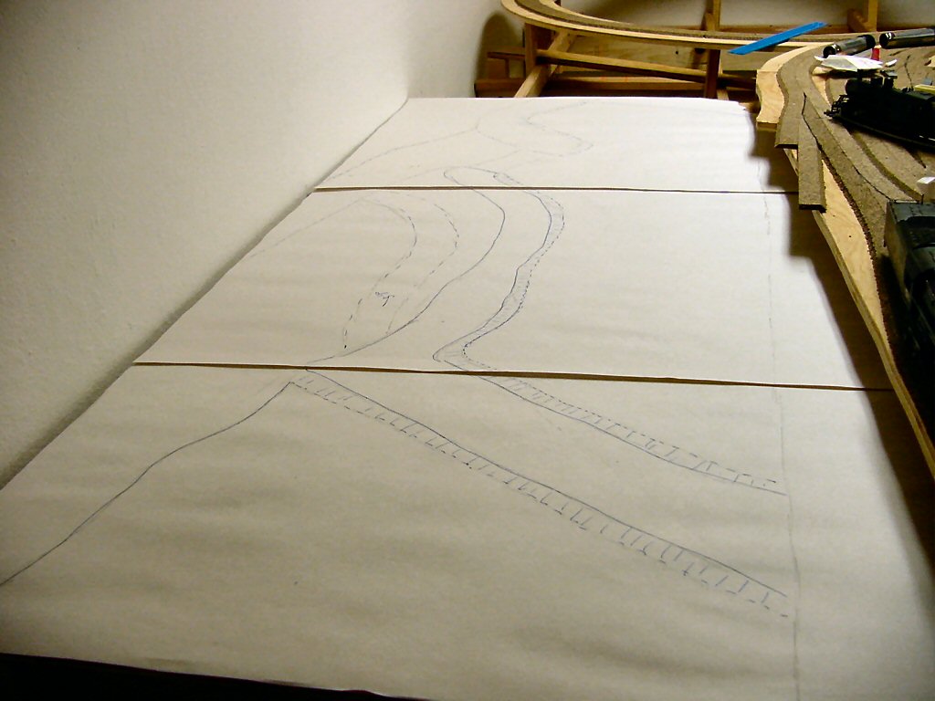
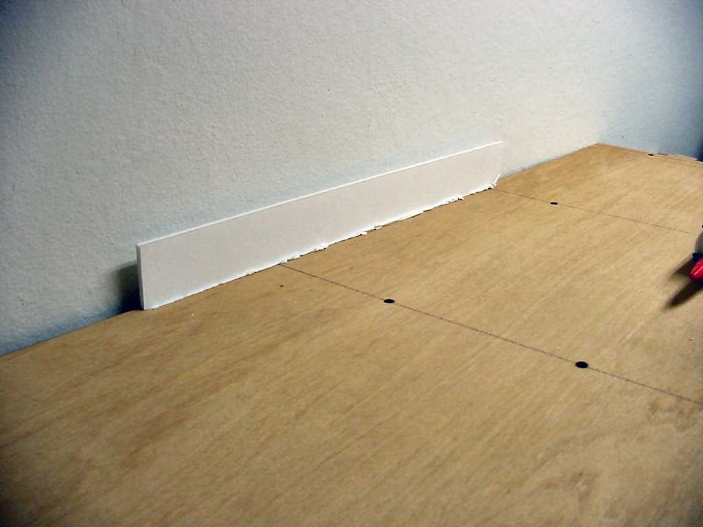
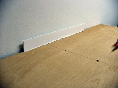
First I cut a sheet of ¼” plywood to fit which runs the full length of this module. This plywood will be the bottom of the bay. Everything goes up from here.


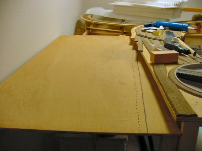
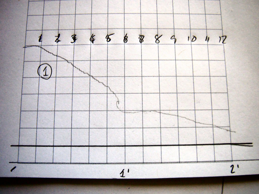
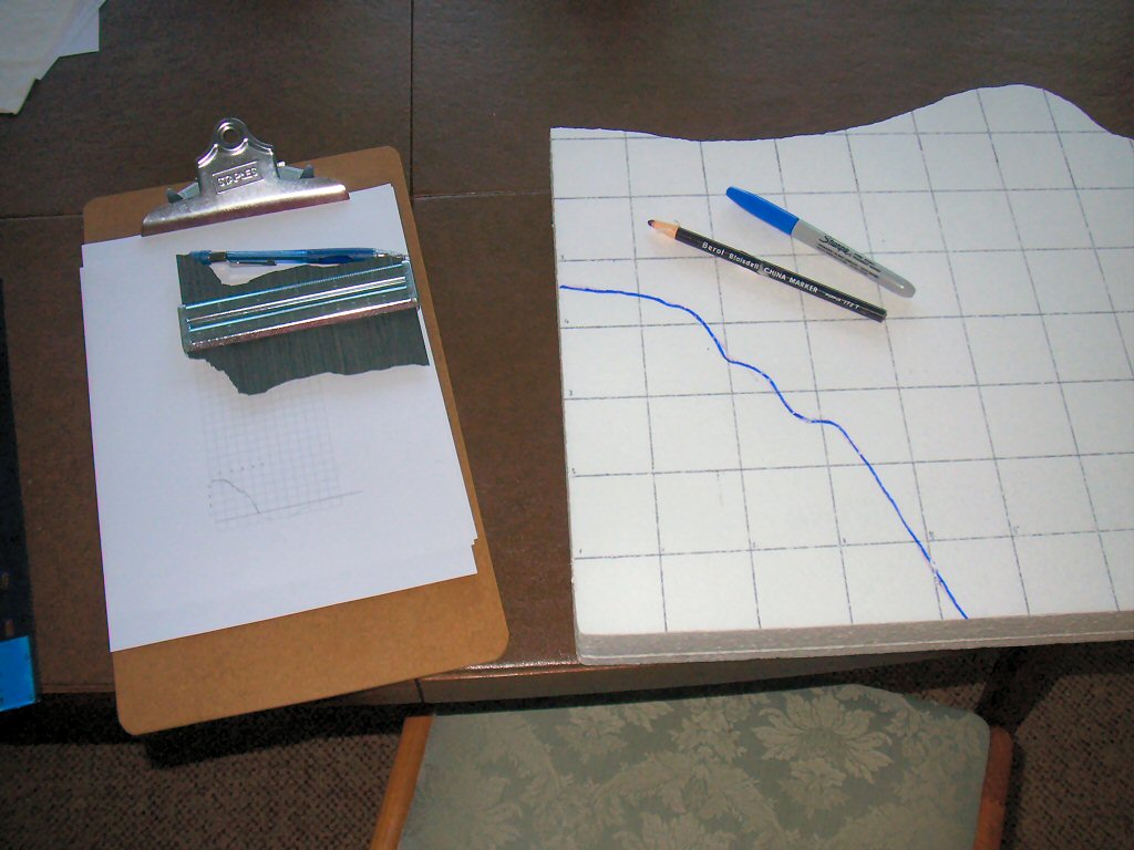
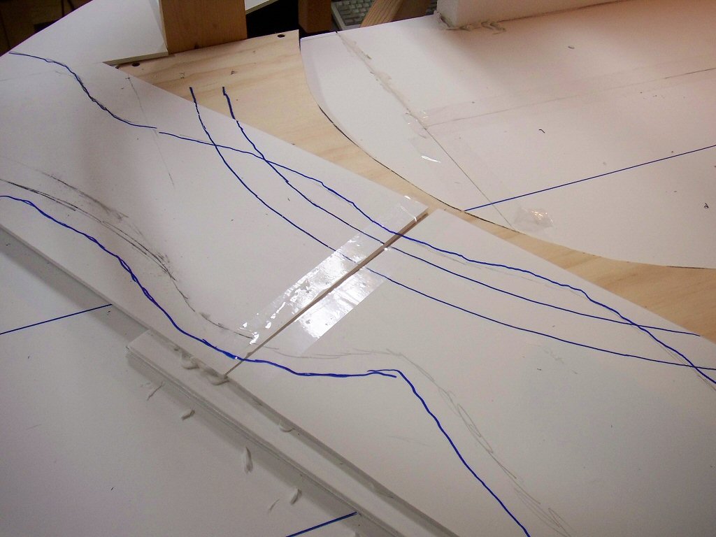
I laid out paper on the plywood and penciled out shapes guided by what I had on the planning model but I always find that I end up making adjustments once doing it full size. Once I was satisfied I re-traced it in pen.


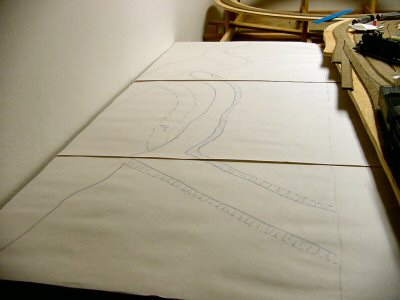
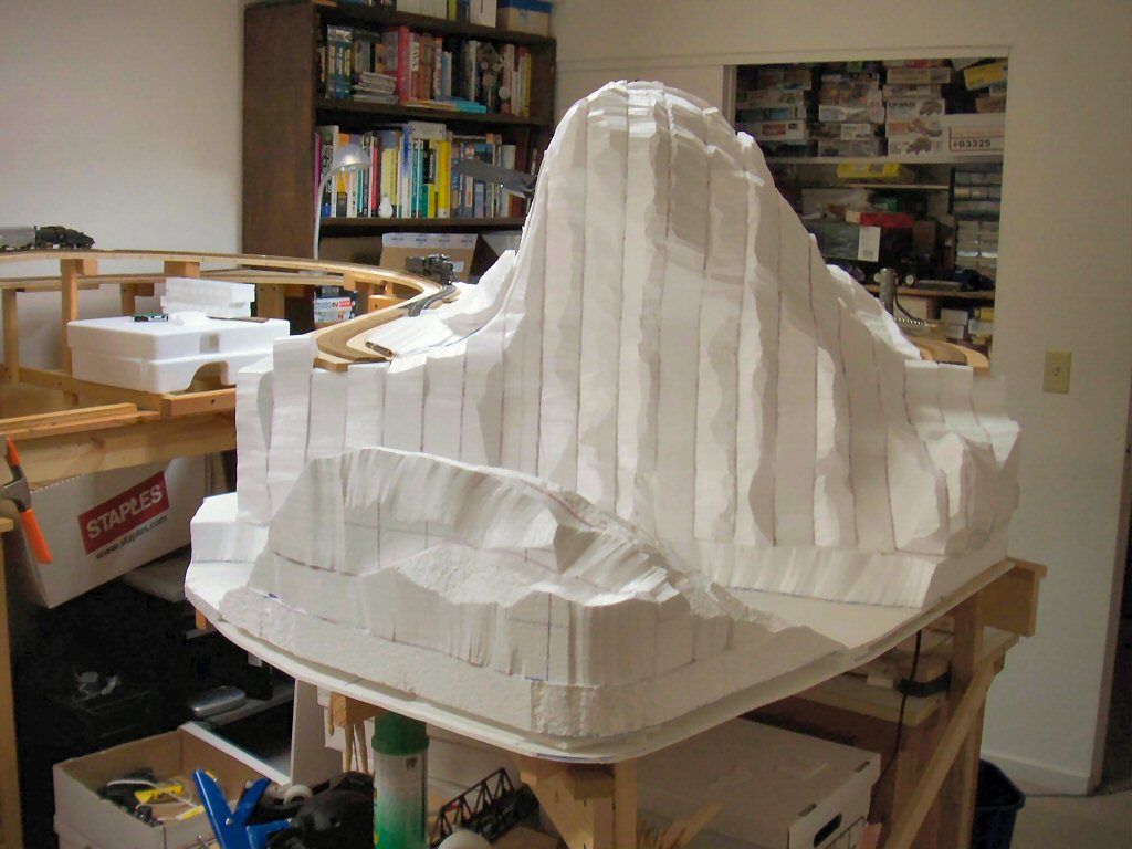
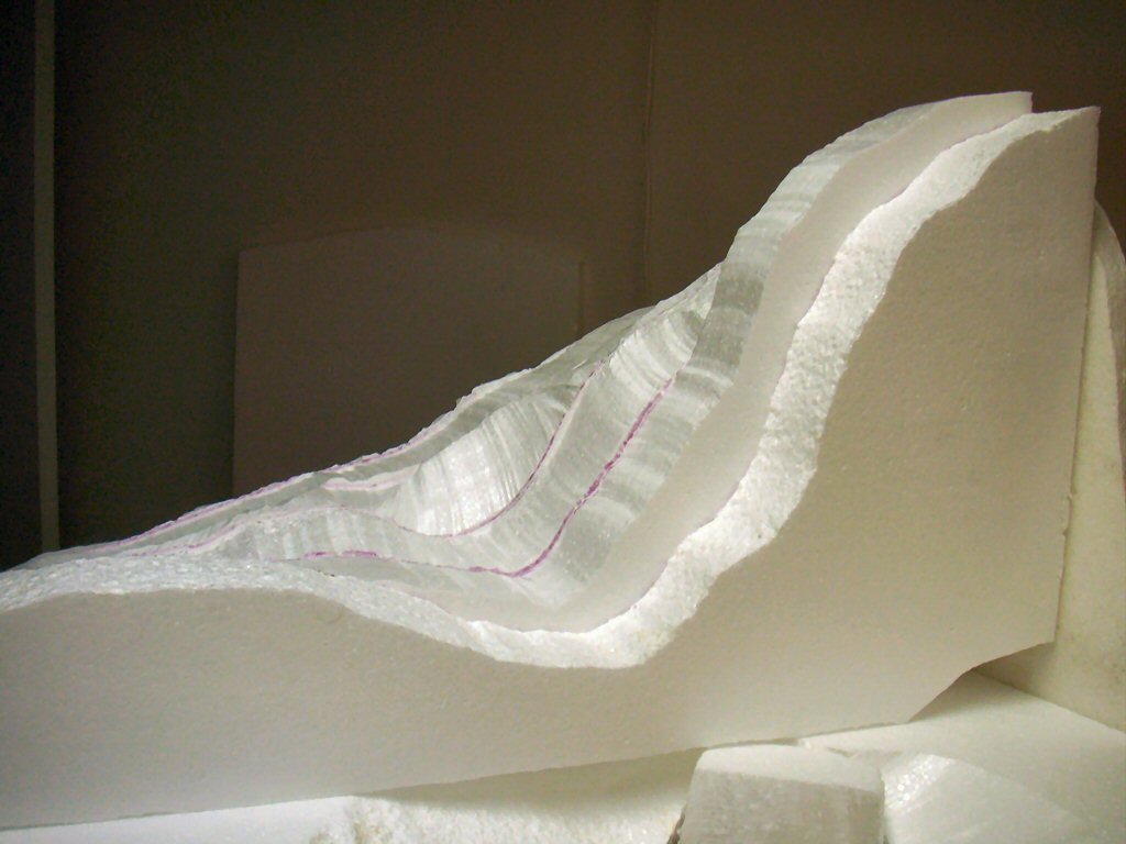
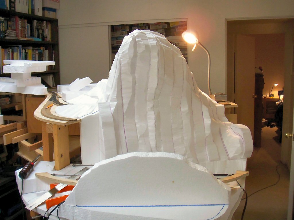
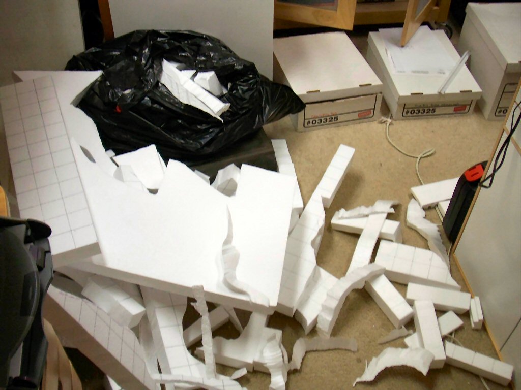
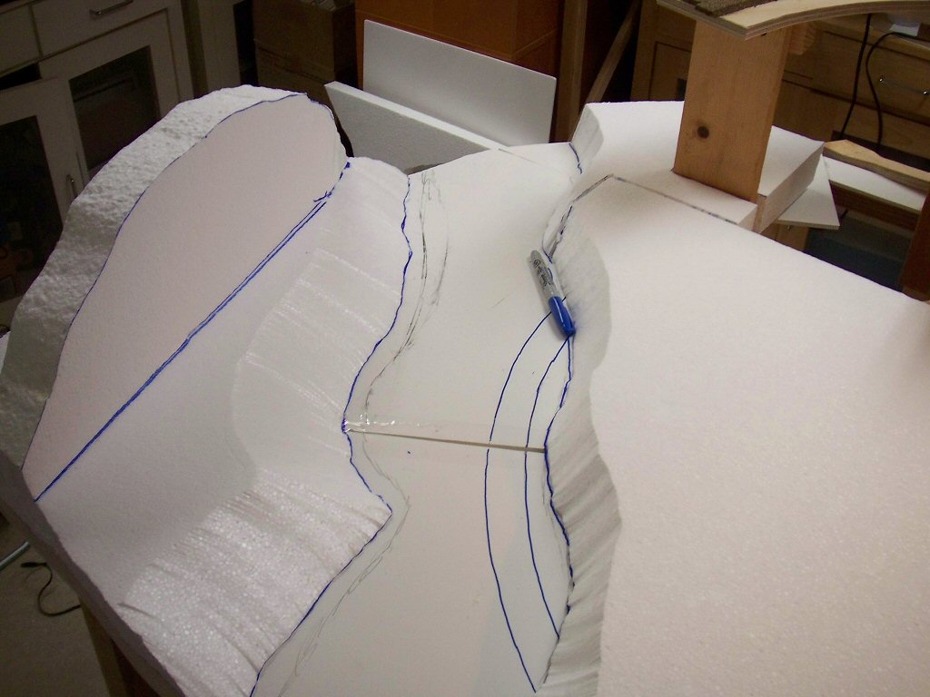
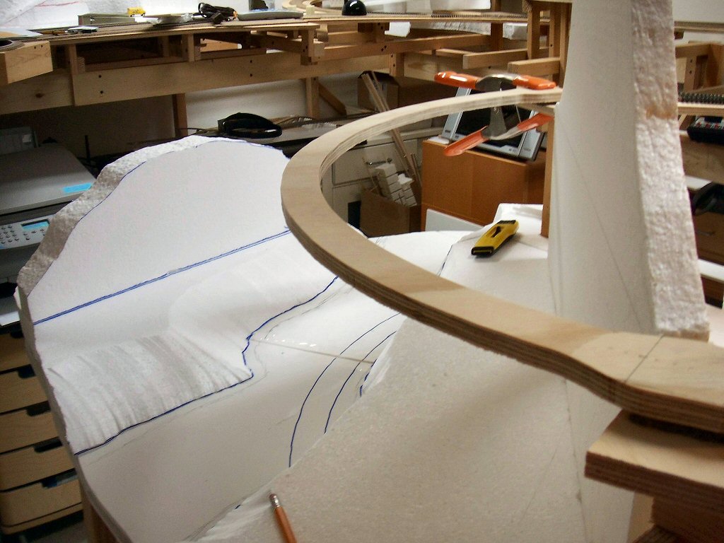
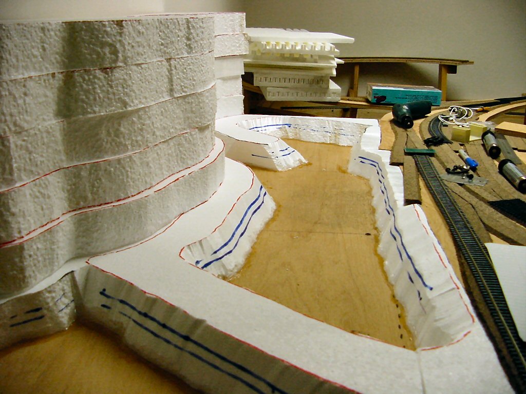
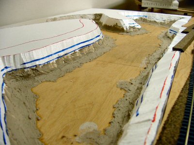
I cut the paper plan into a templates and cut the shape I needed out of 2” thick bead board sheets. I use a Woodland Scenics hot wire cutter and an electric hot knife to cut Styrofoam. I wear a mask for the fumes and do as much as I can outdoors but as far as I’m concerned heat-cutting foam is the only way to go. Here I’m test fitting them before gluing.

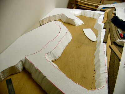
The boat shaped piece of foam board is testing the size of a 60 foot boat.


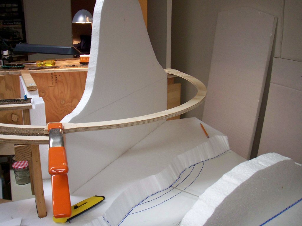
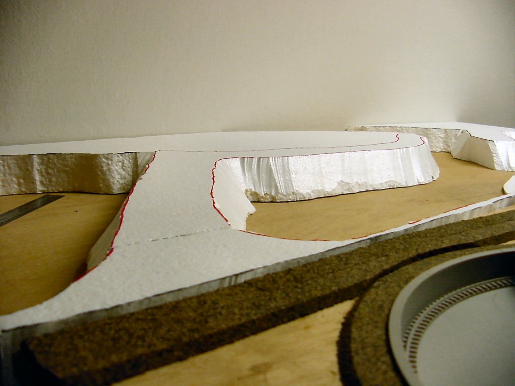
There’s a gap in the back and eventually I’ll be pouring in my bay water so I laid a piece of  3/16” foam core board there as a dam and glued it down with liquid nails.


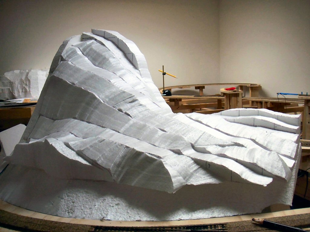
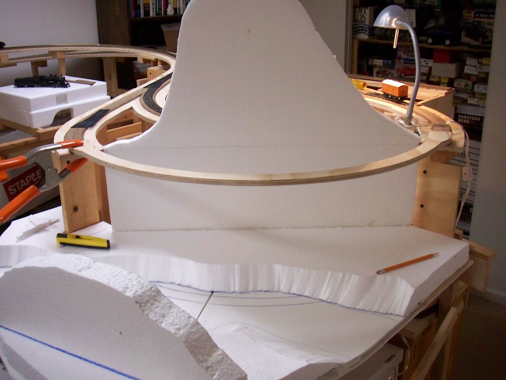
The first base level exactly matches the height of the top of the cork roadbed in the adjacent rail yard (good planning on my part). I cut stacks of 2” foam boards up to until I liked the height. I’ll carve these down with the hot knife and glue them down later.


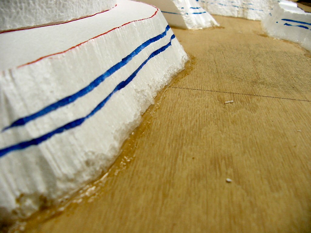
Most materials used to model water (I haven’t decided what I’ll use yet) will seep through any available holes so I sealed the edges with silicon sealant.


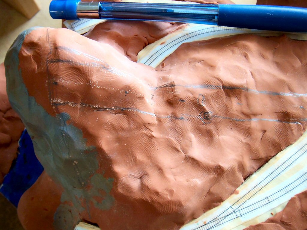
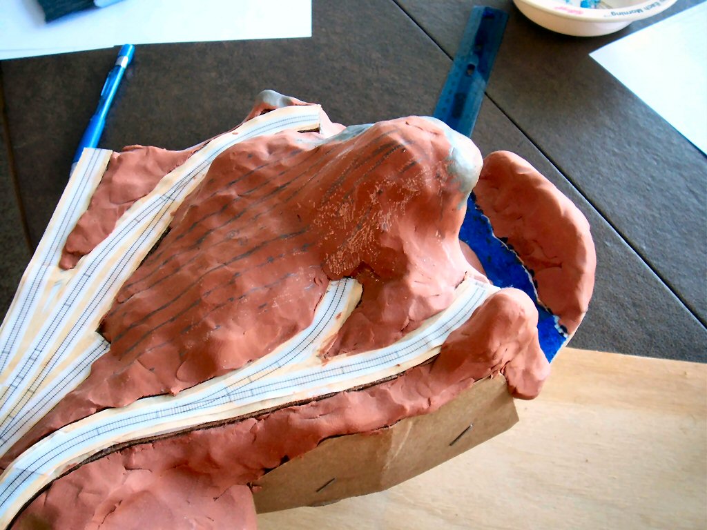
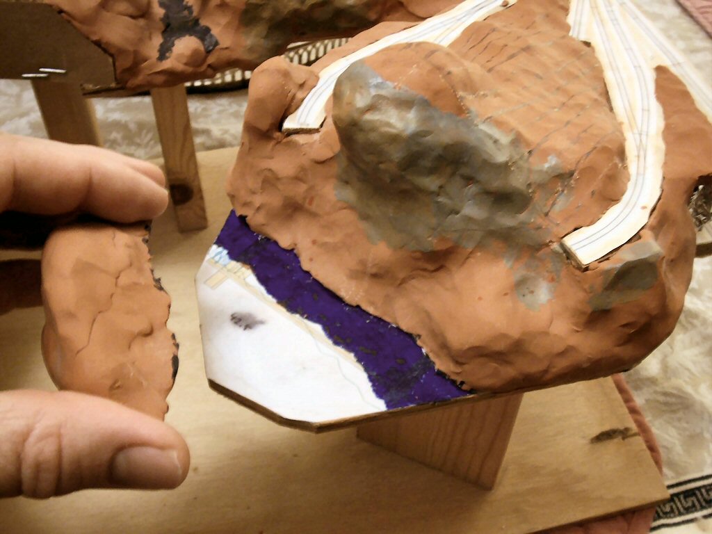
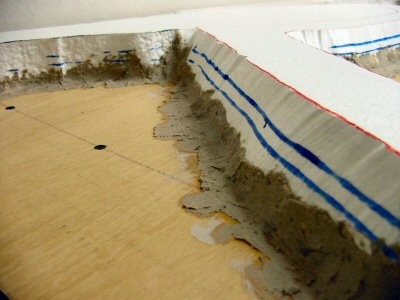
The two blue lines were different ideas I had about the water level. Looking at the photos, Tiburon was (and is) built very close to high tide level so I’ve settled on the higher water mark.

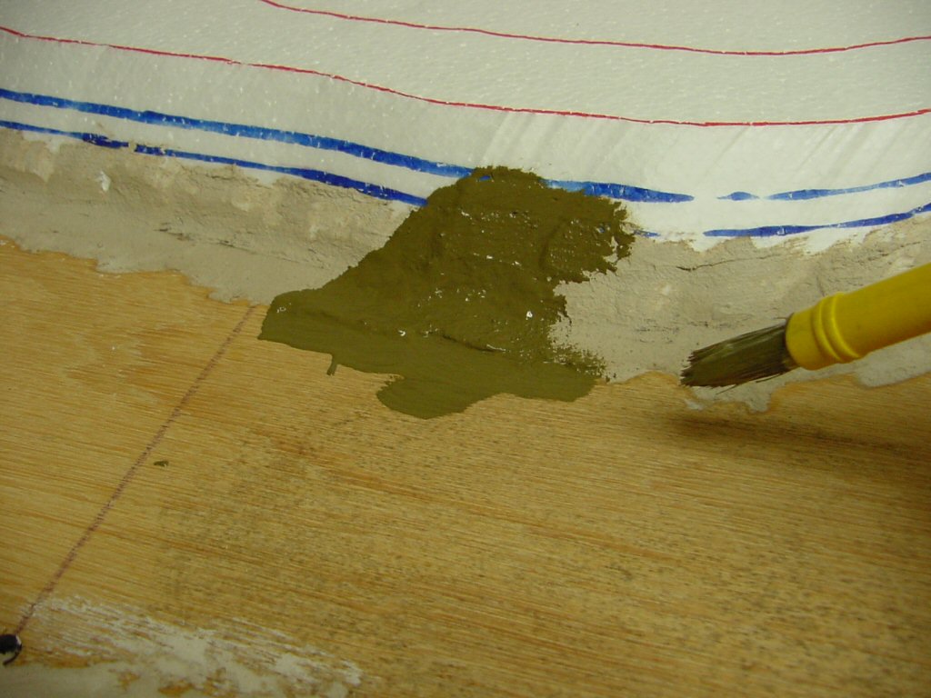
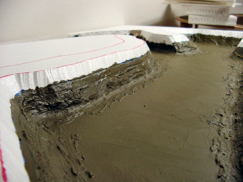
I added a fillet of paper mache. This is needed since most paints refuse to stick to the silicone sealant and I want to start to build up the texture.


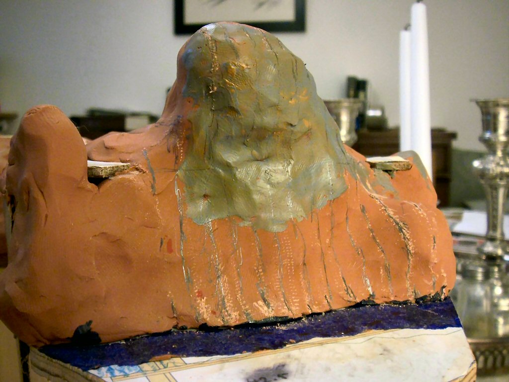
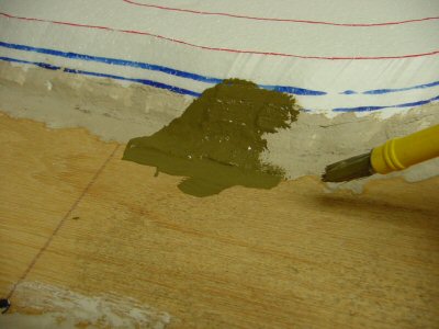
I painted everything from the high water mark down with my “wet mud” color. This is a base color I had made in latex paint and I use it everywhere under dirt. The color ends up basically olive drab. I’ll probably paint black any areas I want to appear as deep water.


Well, this is all I’m going to fit in on Labor Day weekend.

This stage of layout design borrows heavily from architecture and theater. Indeed, examining the definitions of these words you get:

Architecture: The art and science of designing and erecting buildings.

Theater: (the most appropriate of the many definitions) A place that is the setting for dramatic events.

For me these definitions exactly span what model railroad design and construction is and combining them gives a good working definition of model railroading:


Model Railroading: The art and science of designing and erecting a place that is a miniature setting for dramatic events involving trains, terrain, and associated human activities.


When is it the right time to build a planning model? Really, whenever you get a point where you feel you need to “see” things better to proceed deeper.

As I mentioned before I used the 3rd PlanIt CAD program to design my trackplan. While 3rd PlanIt has decent terrain design and 3-D visualization capability, I found it would take me a very long time to use it to design the terrain of my layout so I used the CAD program to design just the track plan and benchwork plan. I decided to use a planning model to work out the way hills, valleys, and streams would work out on the plan.

I chose a large scale: 1:8 to use for the model. This means 1/8” = 1″ (1.5 inches = 1 foot). I happen to have an artists model figure which is about 5 feet 6 inches in height in this scale.


Using the CAD program and my printer I made patterns from cardstock (manila folder paper) and transferred the shaped to ¼” plywood which I cut out with a jigsaw. The ¼” thickness is not important – it’s just what I had lying around in scrap. I used some 1 x 3’s as pedestals to set the scale height of the sections.

As you can see from the photos I broke the layout up into four sections. While the layout is not portable, it needs to be moveable. The height of each section is defined by the lowest terrain planned in that area. I followed to basic height/depth plan Furlow used for his San Juan Central but offset everything higher for my track zero height of 53.5 inches from the floor.


I glued a scale printout of the trackplan onto a sheet of 1/8” plywood and cut the plan out cookie-cutter style out of the thin plywood (this simulated the roadbed roadway I would eventually make for real out of ½” plywood). Then I glued a printout of the trackplan onto the layout sections and used wood screws as risers for the roadbed.


At the time I was worried I had done everything accurately enough. Comparing the model above to the current state of the layout it looks really close.


To actually model the scenery I used Sculpey (http://www.sculpey.com/) which is modeling clay that can be adjusted and shaped indefinitely and then hardened by baking in an oven (275 degrees and 15 minutes per ¼” depth). My model is big but fit nicely in our oven.

I used balls of aluminum foil to create the basic hill shapes and then covered the foil with a skin of Sculpey. Later I used acrylic paint to indicate areas that would be roads and water.


The completed model

Malcolm Furlow’s San Juan Central (SJC) flipped right-left so it matches the basic configuration.

In general I followed the terrain of the SJC since I really liked the SJC looked.

Here I have the figure pointing to the Crazy Horse Bridge.


Tiburbon (a play on the name of the real town of Tiburon, California).


The back of the layout and the Two Tunnels area.

Between this planning model and the CAD track plan I had worked out enough of the details to proceed with construction of my layout. I really found this step a lot of fun and while I feel it is a required step to building a layout I could see building a few of these for fun just to try out different ideas for layout design.