Crazy Horse Canyon


This is taking longer than I would like. I’ll talk about this more later but I’m now seeing that building up a layout out of foam may be a good technique but quite time consuming. 

I’m staring to think that building up out of foam has its place but not as the way to build your entire layout.

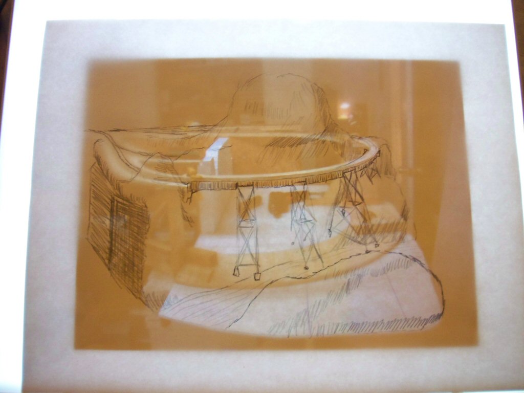
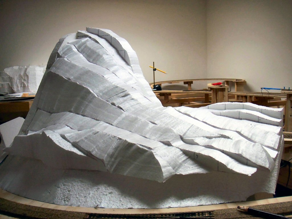
One area it makes sense is around Crazy Horse Canyon since I have a pretty detailed idea how the terrain will be contoured and it will be nearly all rock castings.

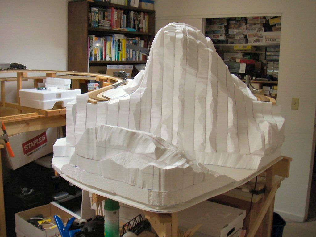
First, I really don’t think building up layer cake style works as well as making vertical slices. I see in the December 2006 Model Railroader that Pelle Søeborg also builds this way.

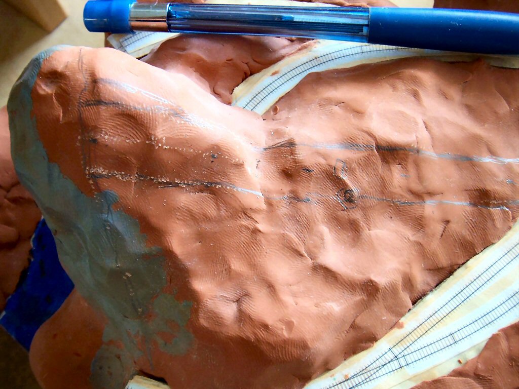
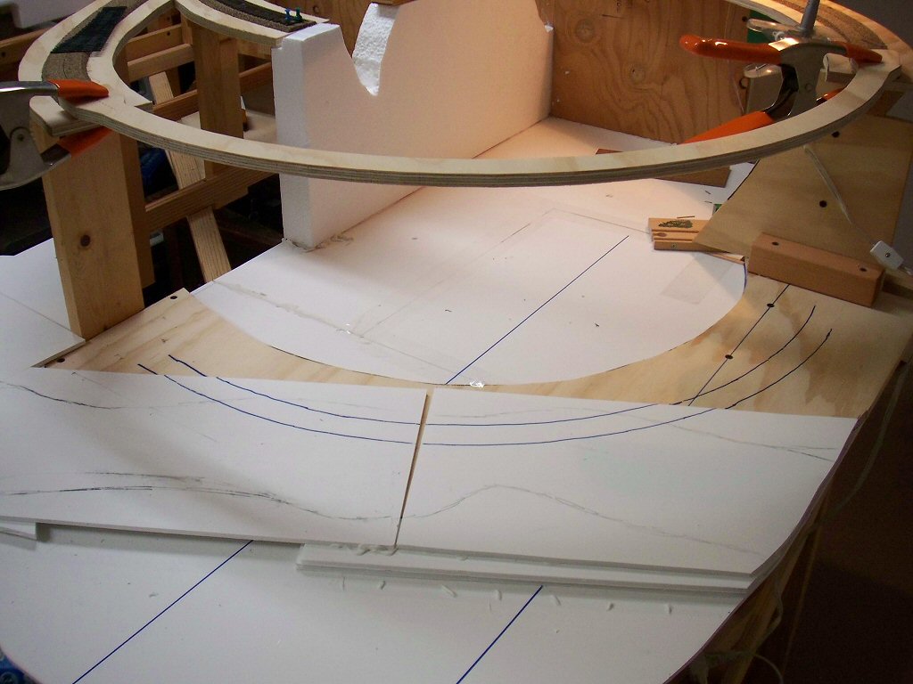
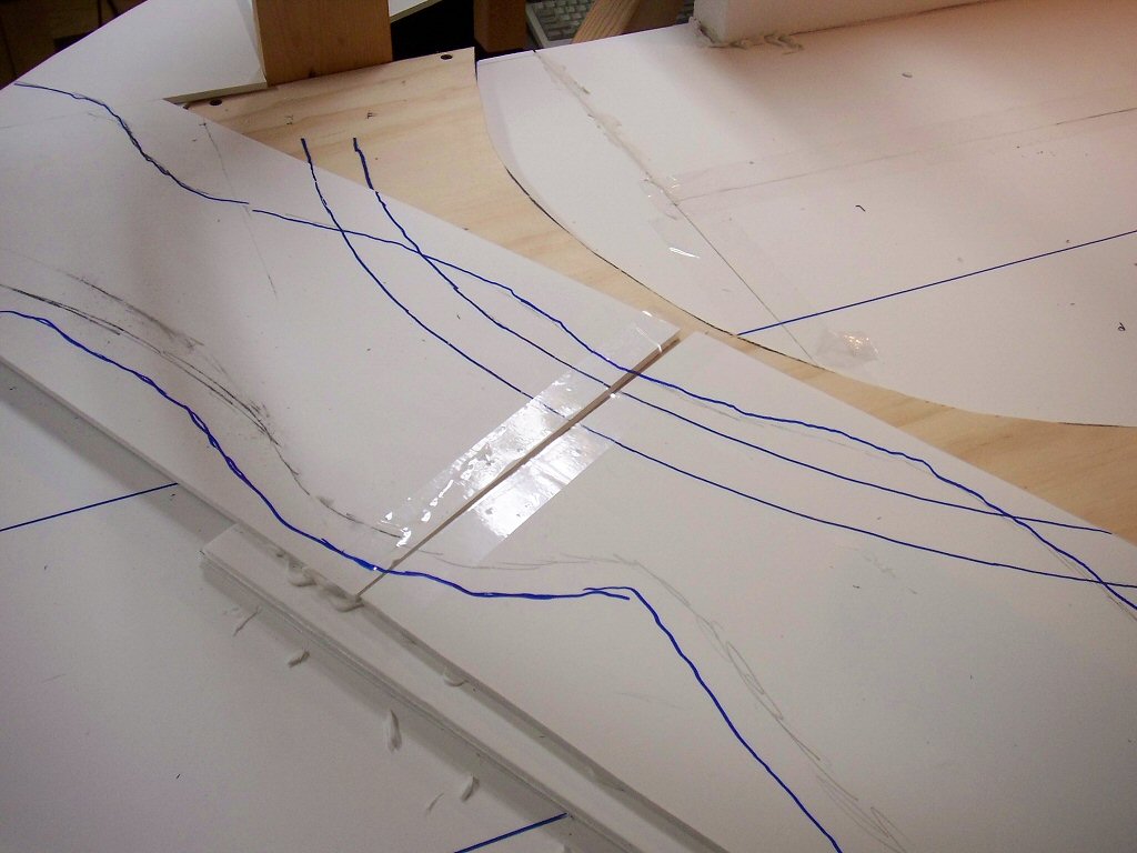
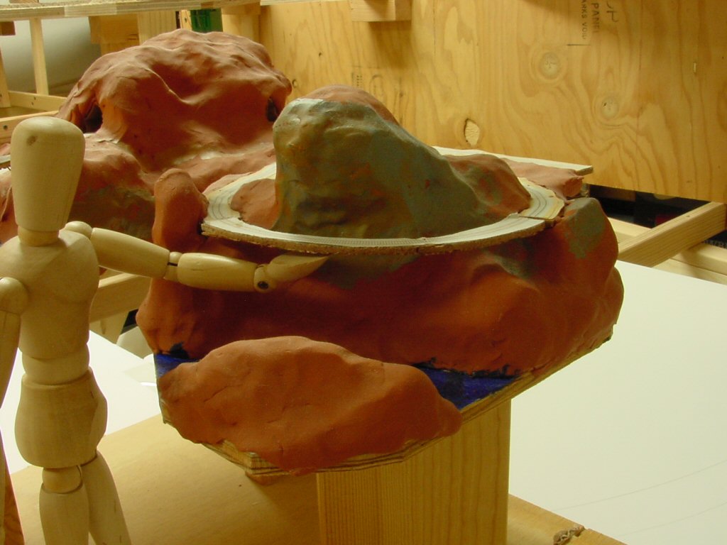
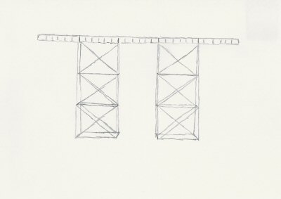
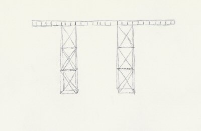
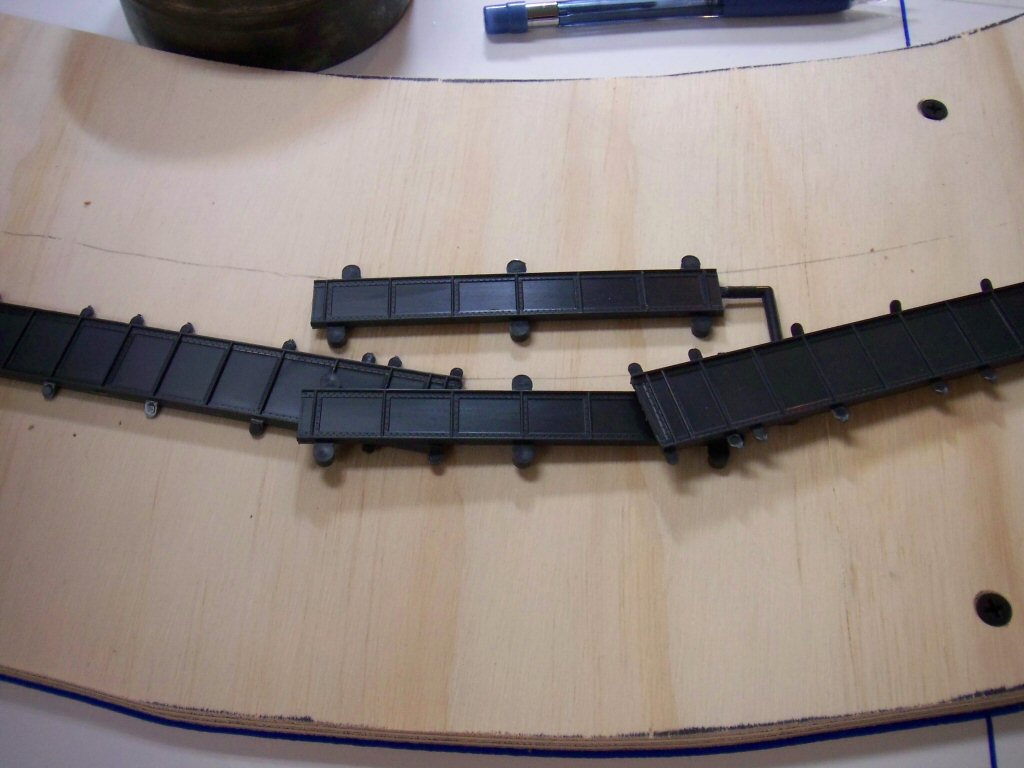
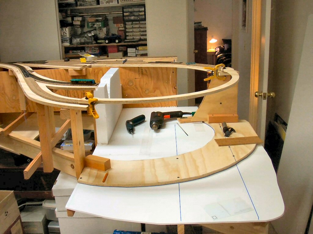
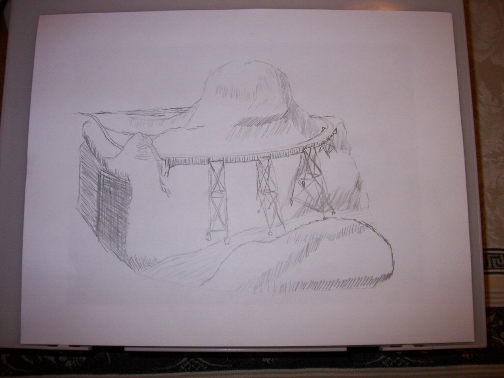
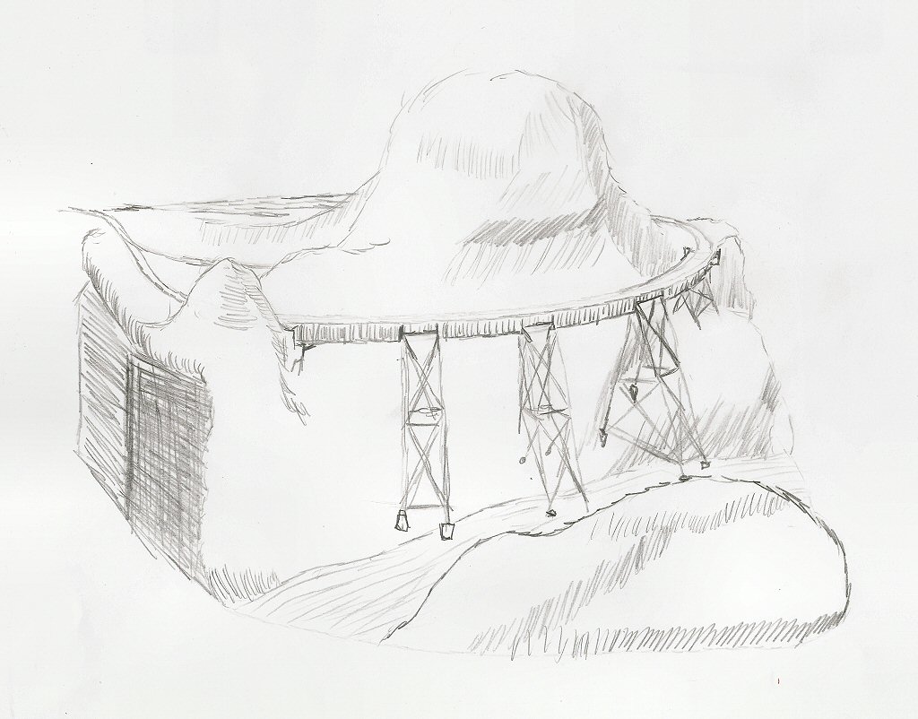
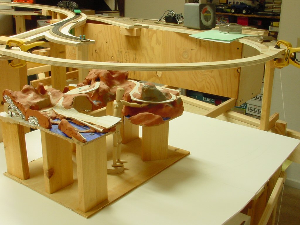
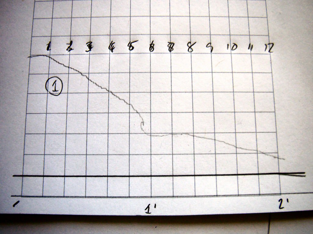
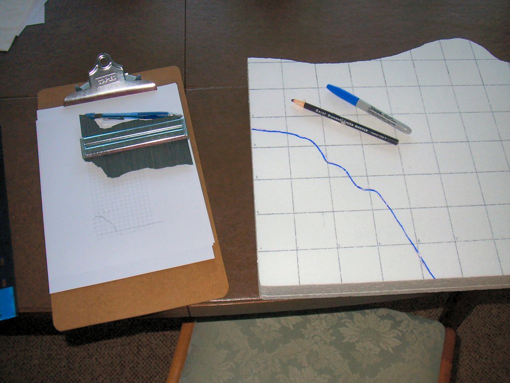
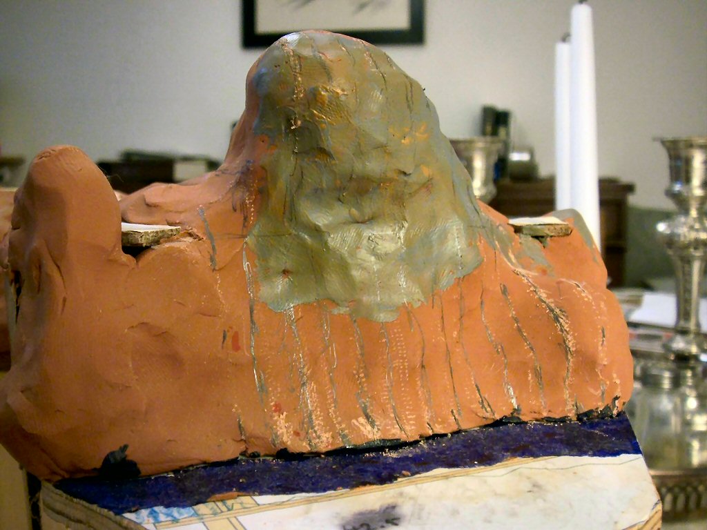
I started by drawing pencil lines on my planning model that I would turn into profile cut pieces of Styrofoam. Next I used a profile gauge to transfer the profile onto a scaled piece of graph paper that matches a 2” square grid.

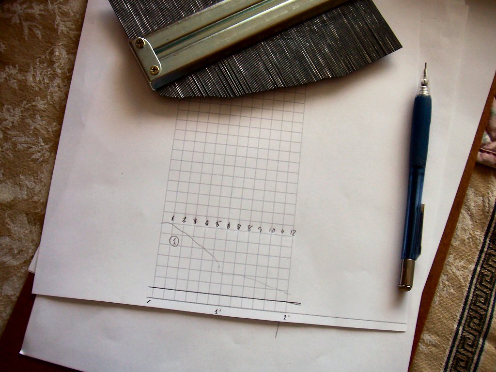
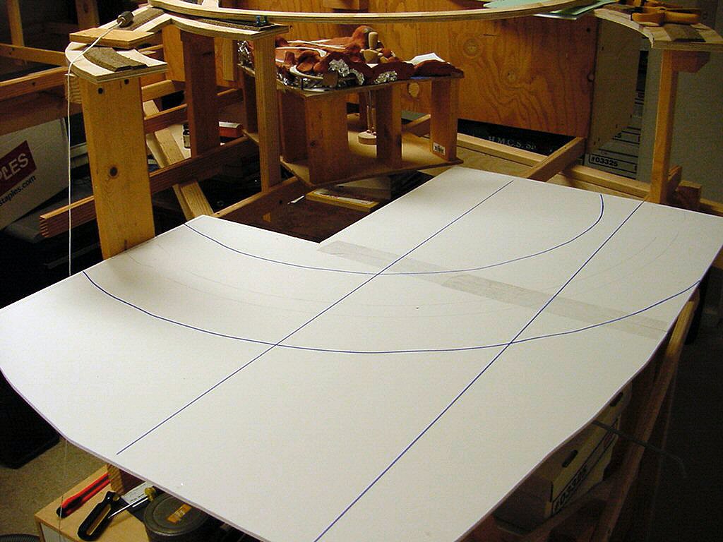
Then I marked my 2” thick 2 ‘ x 4’ pieces of Styrofoam with a 2” grid.

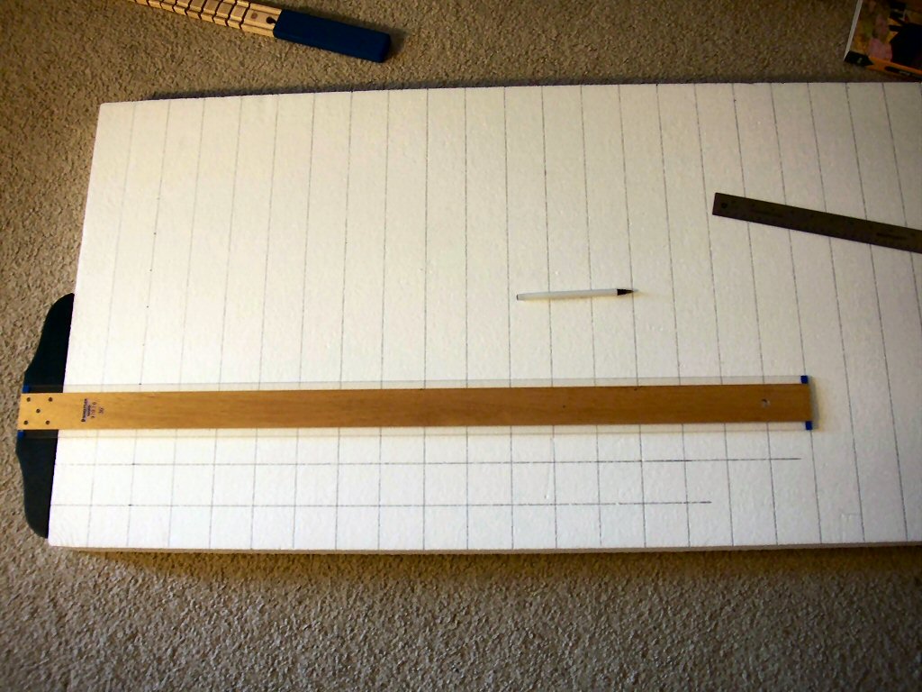
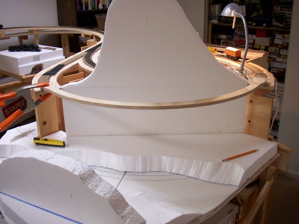
Transfer the contour to the big board.

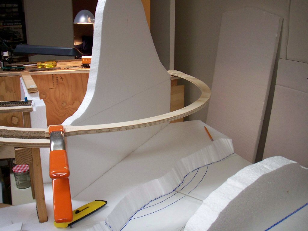
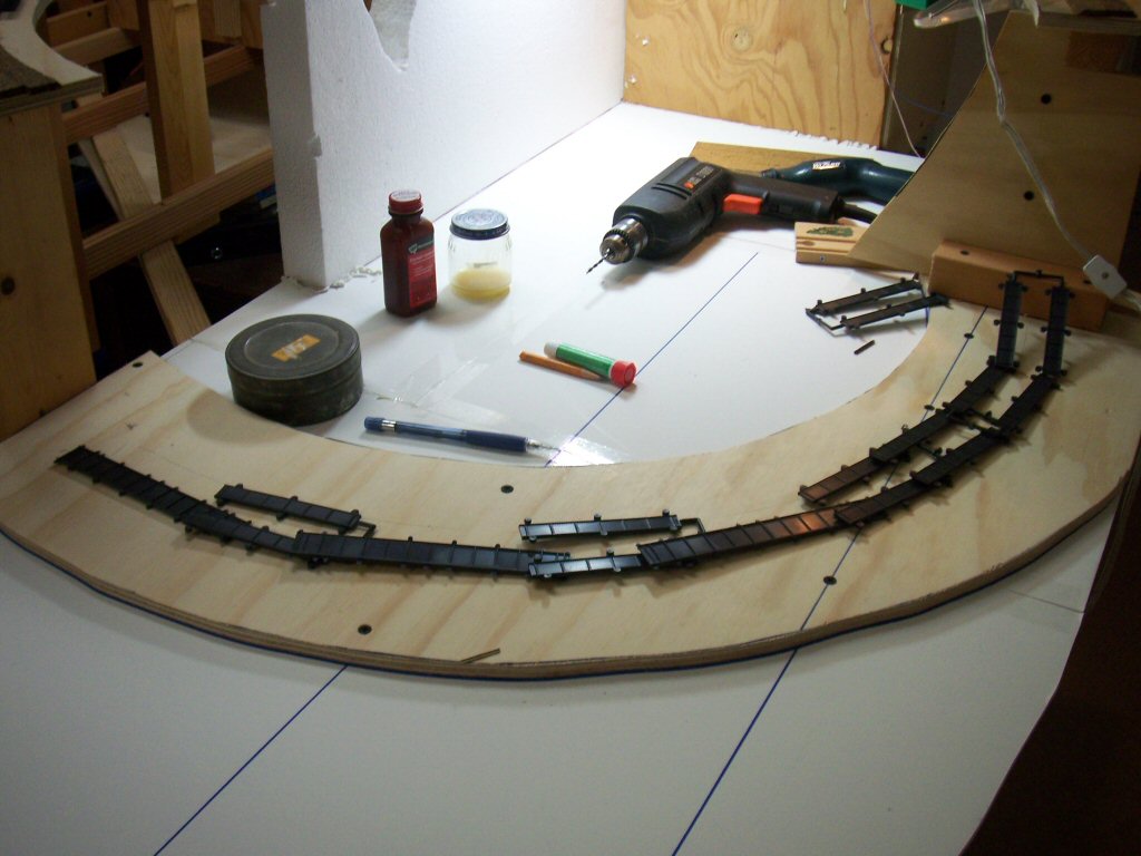
Cut with either a hot-wire cutter or my hot knife. If I can reach far enough I use the wire cutter since it does finer work but if not I use my hot knife which can reach anywhere. Then I place the piece in place.

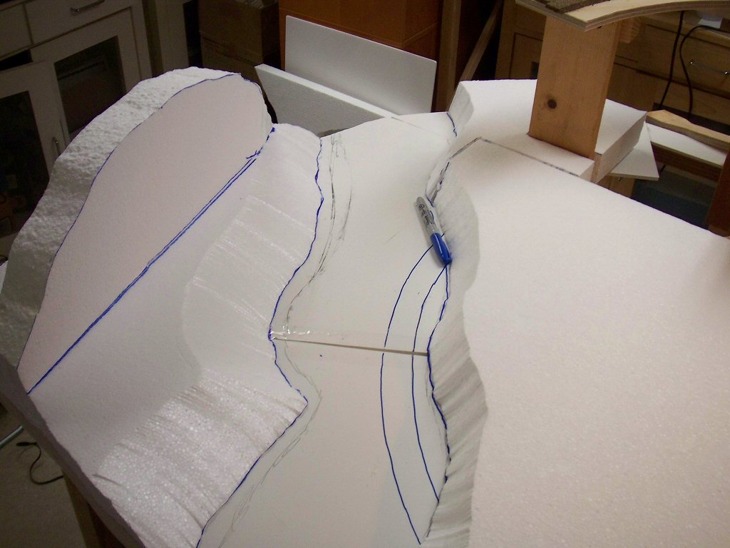
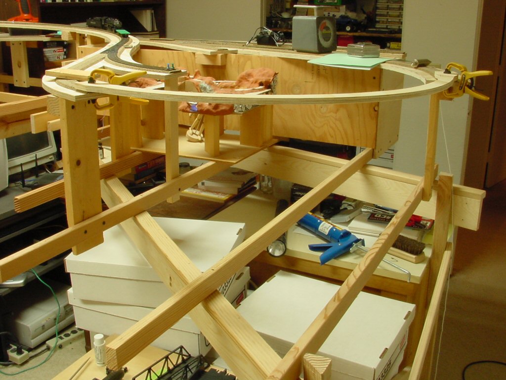
The “back” side of the hill behind the canyon I measured by pressing the contour gauge straight down.

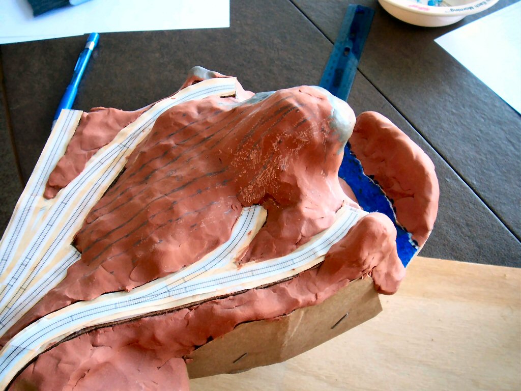
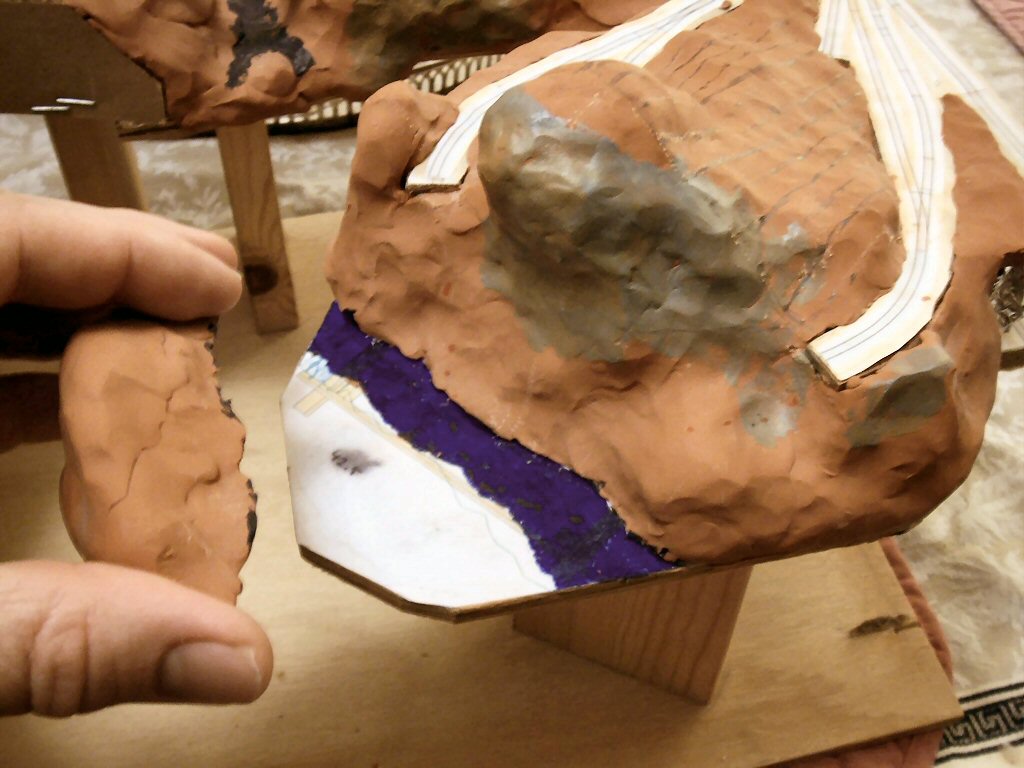
The “front” side of the canyon is mostly vertical and even has an overhang

so I pulled off the bit of modeling clay opposite the cliff and measured it by pressing the contour gauge straight into the cliff face.

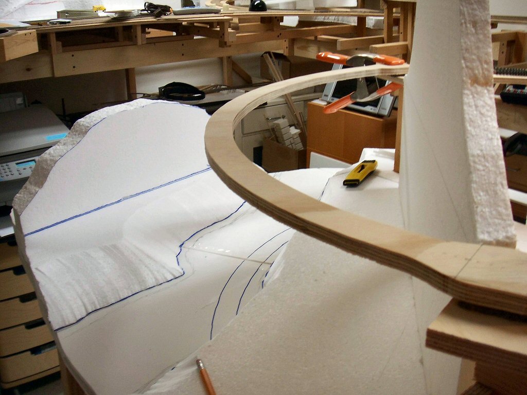
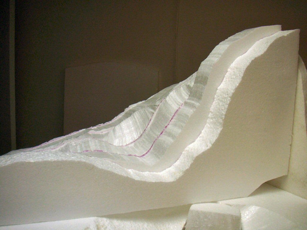
As I add the pieces I place them unglued in position and then go back with a hot wire cutter and trim each piece to more nearly fair into its neighboring slice.

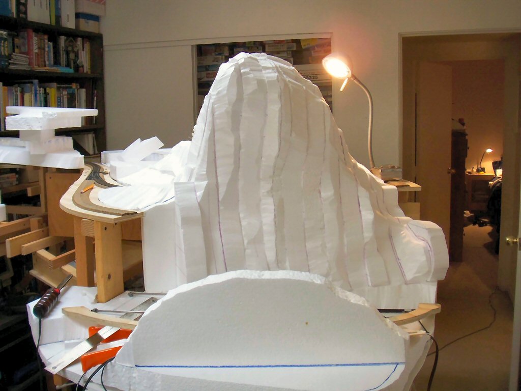
This makes a big mess even when you use hot cutting (although nothing like the mess you make sawing bead-board):

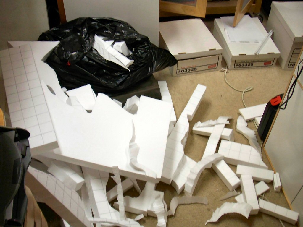
I figure nearly half of the styrofoam you buy ends up as unusable small scraps you have to throw away.

So far I’ve framed the canyon area and made a rough design plan for the bridge. Now I’m starting to rough in the scenery.

First I put down a couple pieces of foam core board to be the riverbed and sketched out outlines of the shore.

Then I cut some 2-inch bead board to fit these lines and the outline of the bench work (I’m going to need to start thinking about fascia material soon!).  I use a hot knife and a hot wire cutter to do all my cutting.

Once I had these flat pieces secured I cut some profile pieces to establish the high points.

Now I need to get some rock castings going.

Now that I’ve framed out Crazy Horse Canyon it’s time to start designing and building the bridge.

Building a big bridge like this is a bit of a chicken/egg exercise. The bridge is actually dictated by the track plan. The scenery is dictated by the bridge but the scenery must be laid down under and around the bridge before the bridge is installed and the bridge legs will have to be adjusted on installation to match the actual contour of the terrain.

I plan on using two Micro Engineering “Tall steel viaduct” kits to build the steel bridge along Crazy Horse canyon.

The total bridge length is 37 inches or 268 scale feet. It is also a continuous 18” radius turn and covers 118 degrees. I’m using two Micro Engineering kits; a 150 ft number 75-514 and one 210 ft kit 75-515. Between them I have plenty of parts.

I really like the Micro Engineering kits but a want a taller, more spindly appearance to the bridge. Following the kit instructions will yield a bridge with proportions like this:

However, I’m going to shorten the tower spans and thereby make the bridge towers have a more tall/narrow look.

The “engineering justification” for this is that the piers have to be rooted in the stream bed and this makes for smaller concrete piers in the stream. This is simply a fiction to justify what I feel are more pleasing proportions.

I have my planning model (photo a top of article) to show basic contours of the scenery but now I want to think about how the bridge will actually look in this scenery.

I laid out the pieces of the bridge to get a rough idea how many piers would be needed and roughly where they would be located.

I overlapped the pieces where the towers would be to roughly account for where I was going to shorten the tower spans. This is just for scenery planning so it only needs to be accurate to the nearest inch or so.

Now take this rough layout of parts and use it to guide a sketch of the bridge and the scenery around it.

Acquiring basic drawing skills really helps you build better models. Pelle Søeborg’s article “Visualize your layout” in the November 2006 MR shows a very effective technique you can use when designing your layout. Søeborg shows using a picture of your layout and then use that as a guide to trace in a sketch of how the area will look with scenery. This is a great fast technique.

I started with this photo I shot of the area around the bridge.

Pelle uses tracing paper but I have a small light table made mainly for tracing and it allows me to use regular paper for my drawings.

Here I’ve taken a print of a photo and placed it on the table.

Then I sketched in the track locations, the bridge and the terrain around the bridge. s

I turn off the light table every now and then to make sure I’ve added everything I wanted.

Once I’m done I take the drawing to my scanner and make a high resolution scan.

Next is the placement of rock castings and building up foam scenery structure.

A photo of my planning model. Following Malcolm Fulrow’s San Juan Central, one of the return loops spans a deep canyon with a bridge that also completes 118 degrees of the loop.

Here we see the yawning gap where the bridge, river, and a canyon will be built. While I was cutting out roadway I carefully cut a piece of 1/2–inch plywood to be a template for the bridge. Below I’ve clamped it temporarily into place.


I’m building up my scenery from Styrofoam but I decided it would be nice to have a base to work up from so I cut a couple pieces of foam core board to fit the area. Before attaching to the frame I traced out where the underlying studs were and traced out an 8-inch wide semicircle where I would lay down plywood to be a firm footing for the bridge.

Using construction adhesive and drywall screws I attached the foam and the wood to the bench work and weighted everything down with books until the adhesive set.

Using the bridge template I can see that I’m really going to like how the is going to look.

Next step is to get the river and scenery roughed in. Below I’ve placed the planning model below the bridge template.