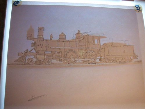
Small, nimble on the rails and with beautiful proportions, the classic 4-4-0 “American” has always been one of my favorite engine types. As I mentioned in my last post, the Northwestern Pacific Railroad was powered almost exclusively by small 4-4-0 and 4-6-0 engines. This is one of the great things about modeling the NWP on the limited size of a model railroad since small engines help create the illusion of greater layout size and mainline distance.
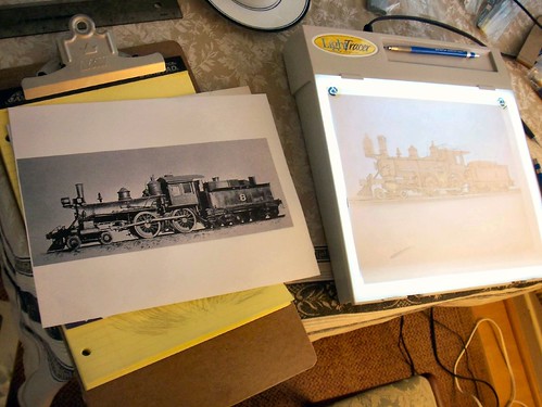
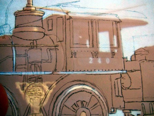
Exact RTR (ready-to-run) models of NWP engines are not available. Consistent with my overall modeling philosophy (plausible but free-lanced), I’m going to examine the engines of the NWP and build engines for my layout that are consistent with the spirit of the prototype. My goal is to build plausible and reasonable, while not exact, models. Understanding the prototype well enough to build things and make decisions consistent with the way the builders and mechanics of the NWP did things is what I enjoy.
The Americans on the NWP in the 1920s fell into two broad groups: old engines built in the 1870s and 1880s — some twelve engines and a “new” group of seven built between 1904 and 1914.
The Old Engines
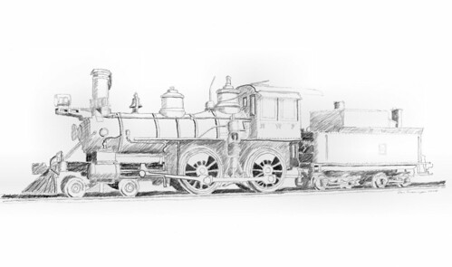
By the 20s, the older 4-4-0s had been in service between 40 and 50 years and had been significantly updated and altered from their as-built appearance. As built the engines would have looked much like these shown below:
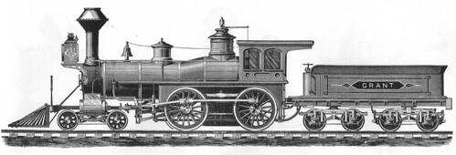 Grant 4-4-0 1873
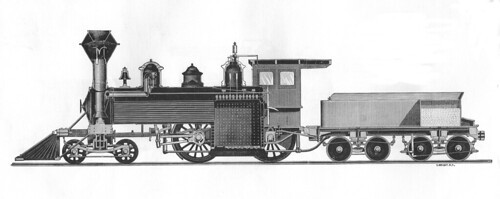
 Baldwin 4-4-0 1871
Both of these engines are standard “catalog” offerings and are therefore typical engines. Compared to the mechanical standards of the 1920s these engines are missing many pieces of equipment:
1920-29 Standard Equipment:
- Engine brakes
- Knuckle couplers
- Air pumps and associated hardware
- Electric lights, generators and associated equipment
- Oil burning modifications (in the NWP case)
While engines may have left the factory looking pretty similar, railroads would generally shop engines only when something broke or needed to be done to meet new requirements (compatible couplers, air brakes, etc.). Individual engines in their 50 year trek to their 1920 appearance would have been shopped and upgraded on unique schedules. In this way each of the old Americans on the NWP looked quite different from each other by the 20s.
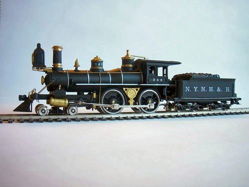
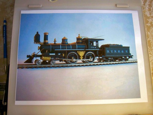
NWP 8 Engine 8 was an 1881 Baldwin product with 63” drivers, 15×24 cylinders and weighed 71,000 lbs. By 1915 it looked like this:
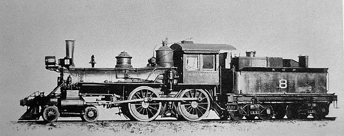
Engine 8 has received minimal modification beyond the standard equipment listed above, a new metal cab, and a new pilot. This is probably not what the engine looked like by the 1920s but I love the proportions of this engine and will likely model it as seen above.
NWP 9 An 1883 Grant product, number 9 had 59” drivers, 16×24 cylinders and an 86,300 lb. engine weight. Number 9 was heavily modified in its lifetime and in the 1920s probably looked something like this 1935 view.
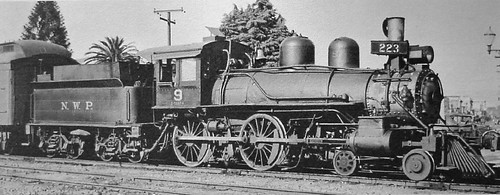
Engine 9 has an entirely new boiler and obviously mismatched pilot truck wheels.
Transition between the Old and New 4-4-0s
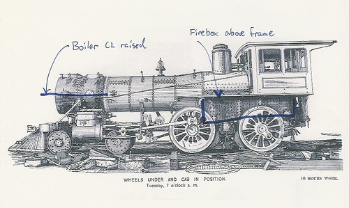
Boiler location: In the 20th century as scientific principals were increasingly applied to locomotive engineering, an emphasis grew on firebox design, boiler pressure and superheating. For the classic 4-4-0 (shown in cutaway below) the location of the firebox low between the engine frames severely limited the size of the grate and therefore the amount of boiler horsepower that could be generated.
The solution was to raise the boiler centerline so that the bottom of the firebox was completely above the engine side frames. As early as the 1888 view shown below this techniques came into use. However, while wider than before the firebox is still constrained to fit between the driving wheels.
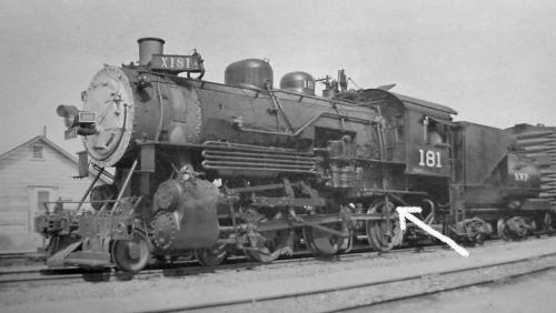
One of the ultimate limitations on the 4-4-0 design is that increasing the firebox size further was never seen as practical. On more modern engines with different wheel arrangements the boiler was raised even higher so that the firebox and grate could be carried completely above the driving wheels and widened to the width of the engine. NWP 4-6-0 number 181 below shows this kind of configuration.
Extended firebox: Comparing the Baldwin 1871 with the PRR 1888 drawing also note the difference in how far the smoke box (the part of the boiler the smokestack is mounted on) extends forward. To hopefully enhance complete combustion, the “extended” smoke box became common (but not universal) on new and rebuilt engines.
Superheating: Superheaters were added to locomotives by changing the boiler design such that steam lines were fed back into widened fire-tubes in the boiler increasing the temperature of the steam and thereby increasing the amount of work the steam could do. This reduced fuel and water consumption for a given amount of power produced. On an old engine superheating is typically only signified by the change from slide valves to piston valves .
Variously updated 4-4-0s on the NWP in the 1920s
This is not a complete breakdown and I picked the following engines because I find them the most interesting.
NWP 10 was a twin sister engine to number 9 (Grant numbers 1665, 1664, respectively) but by 1920 appeared highly modified and updated.
Fully updated with all the modern (1920s) conveniences. Slide valves (superheated), new boiler, air and electrical equipment.
NWP 17 was a Rogers 1889 product with 63” drivers, 17×24 cylinders, and 87,300 lb. engine weight.
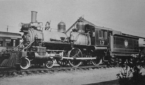
In this 1927 view the engine appears to still have its original boiler since the steam dome is old-style location directly over the firebox and the smoke box is not extended forward. The engine has air and electrical equipment.
NWP 20 was a Rogers 1884 product (older than 17 above) with 62” drivers, 18×24 cylinders and 93,800 lb. weight.
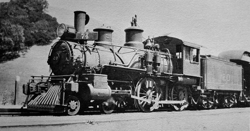
In this 1923 photo the fluted domes on number 20 might lead you to think that this is the original boiler. However, my best guess is that the boiler was added around 1917 and the old domes were apparently reused.
NWP 21 was a Baldwin 1904 product with 69” drivers, 18×24 cylinders, and 117,350 lb. weight.
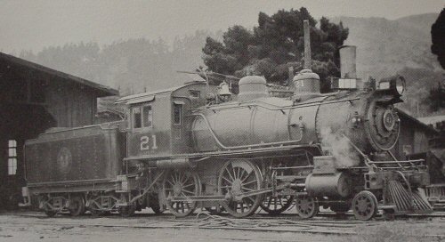
What a difference a few years makes! Number 21 is much heavier than the older engines and in this 1936 photo looks quite modern with the exception of the slide valves.
NWP 22 was a 1908 American product with 69” drivers, 18×24 cylinders, and 128,500 lb. engine weight.
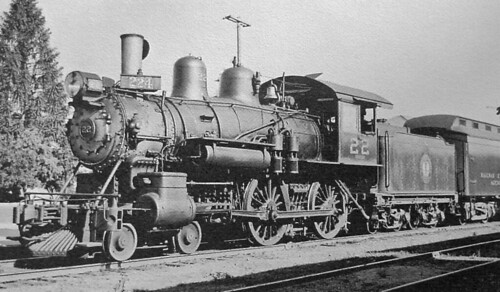
Fairly modern engines but still with slide valves in this 1931 view so presumably not superheated.
NWP 52 was one of the last batch of 4-4-0s purchased by the NWP in 1914. These had 63” drivers, 19×26 cylinders and a hefty 158,500 lb. engine weight.
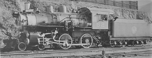
These engines were more than twice the weight of old number 8. Note the modern piston valves and Walschaerts valve gear.
Southern Pacific 4-4-0s
For comparison and more modeling ideas I have some photos of 4-4-0s from the Southern Pacific since SP was one of the NWPs corporate parents and some mechanical influences are evident.
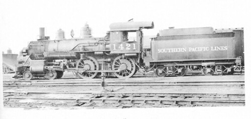
SP 1421 is shown in 1924. The thing I like is the headlight moved to the center of the smoke box front per SP practice.
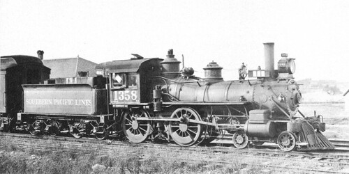
SP 1358 is shown in 1923 and other than air and electrical is looking pretty old fashioned indeed. The relatively un-altered appearance of this engine is my justification for carrying forward NWP 8′s ultra-cute 1915 appearance forward to the 20′s.