Layout Progress


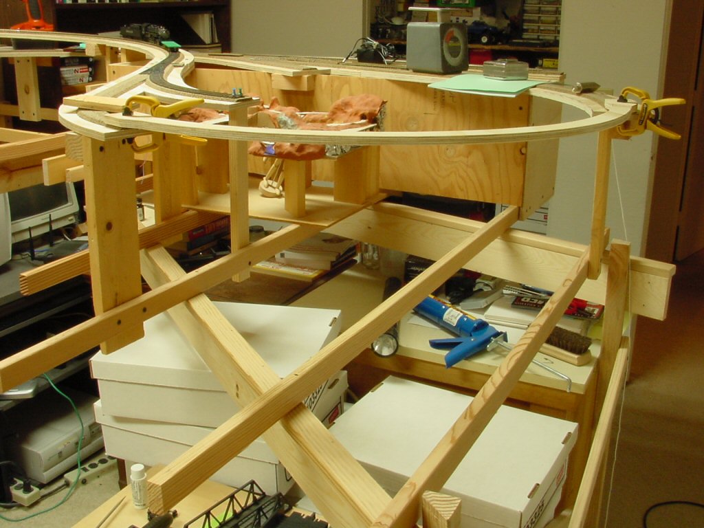
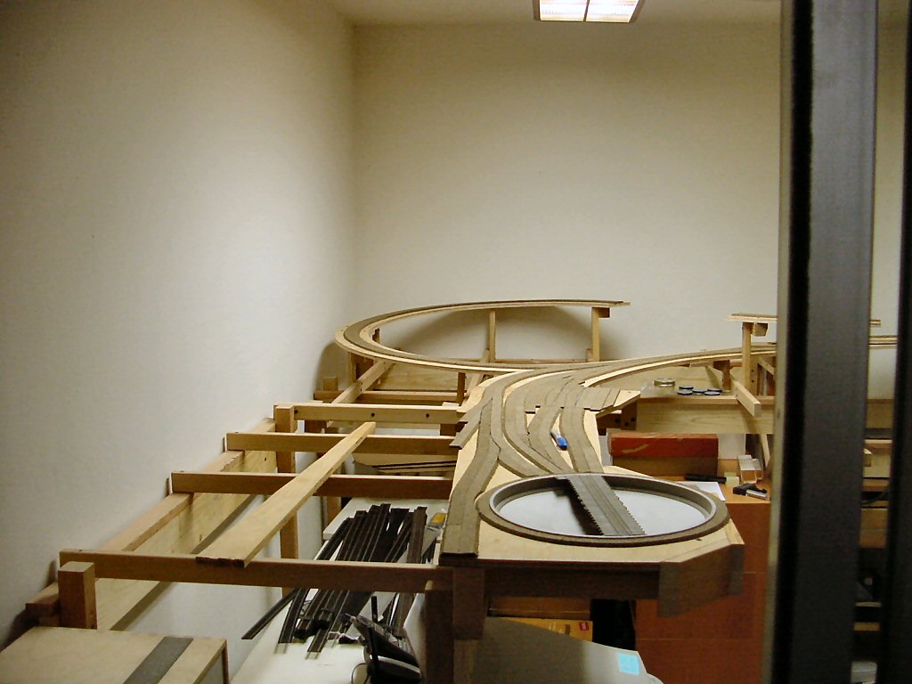
Now that I’ve framed out Crazy Horse Canyon it’s time to start designing and building the bridge.

Building a big bridge like this is a bit of a chicken/egg exercise. The bridge is actually dictated by the track plan. The scenery is dictated by the bridge but the scenery must be laid down under and around the bridge before the bridge is installed and the bridge legs will have to be adjusted on installation to match the actual contour of the terrain.

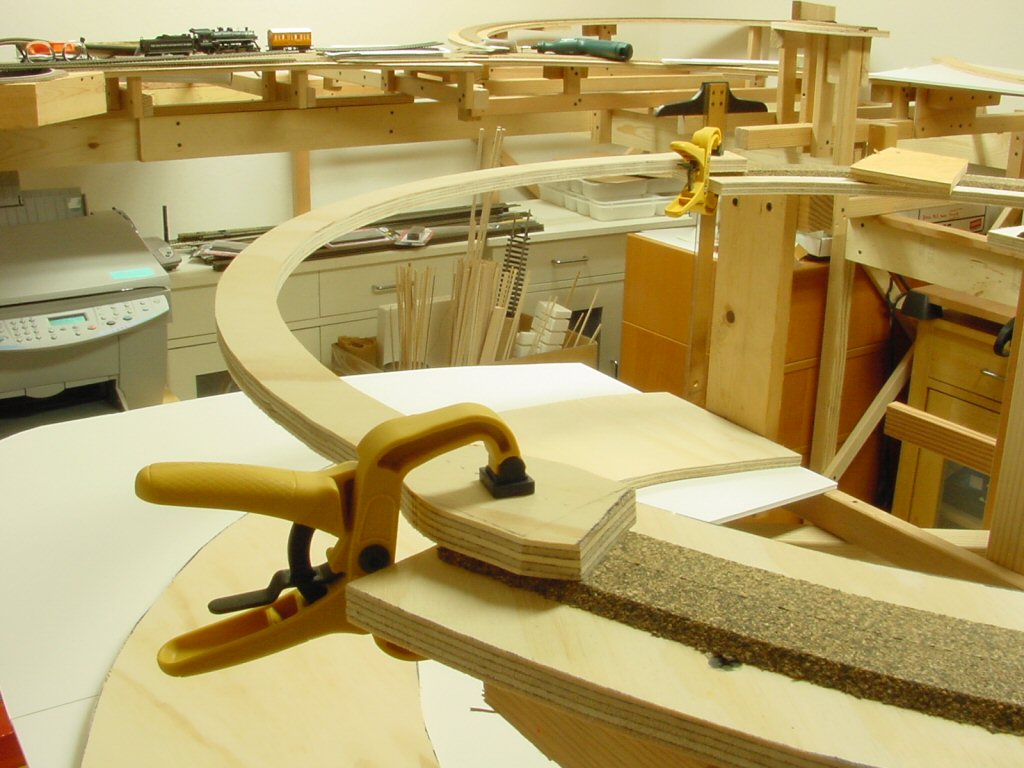
I plan on using two Micro Engineering “Tall steel viaduct” kits to build the steel bridge along Crazy Horse canyon.

The total bridge length is 37 inches or 268 scale feet. It is also a continuous 18” radius turn and covers 118 degrees. I’m using two Micro Engineering kits; a 150 ft number 75-514 and one 210 ft kit 75-515. Between them I have plenty of parts.

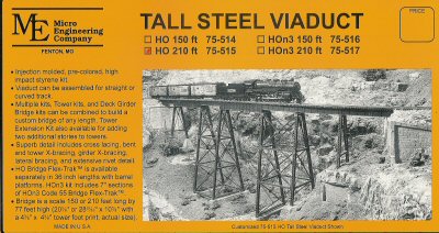
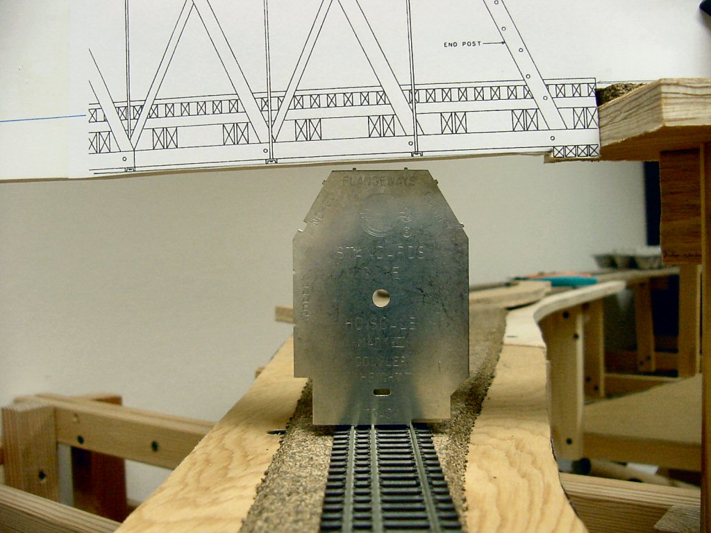
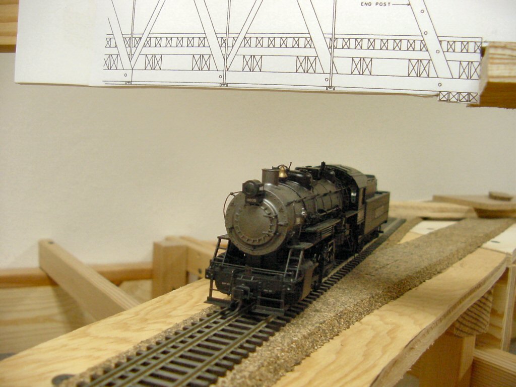
I really like the Micro Engineering kits but a want a taller, more spindly appearance to the bridge. Following the kit instructions will yield a bridge with proportions like this:

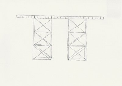
However, I’m going to shorten the tower spans and thereby make the bridge towers have a more tall/narrow look.

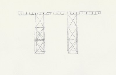
The “engineering justification” for this is that the piers have to be rooted in the stream bed and this makes for smaller concrete piers in the stream. This is simply a fiction to justify what I feel are more pleasing proportions.

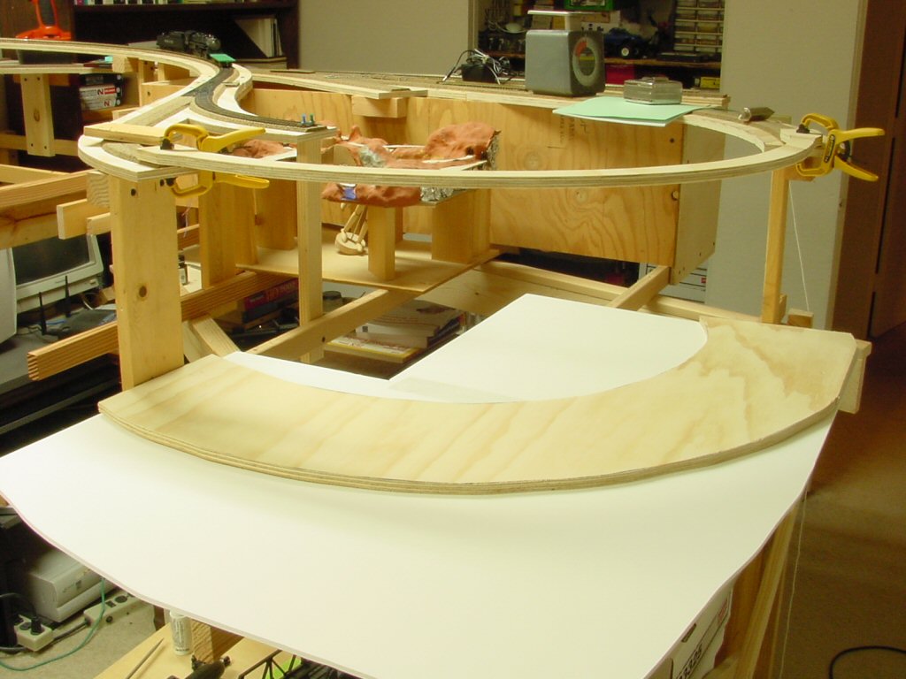
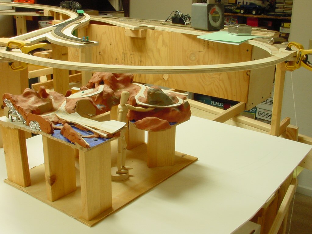
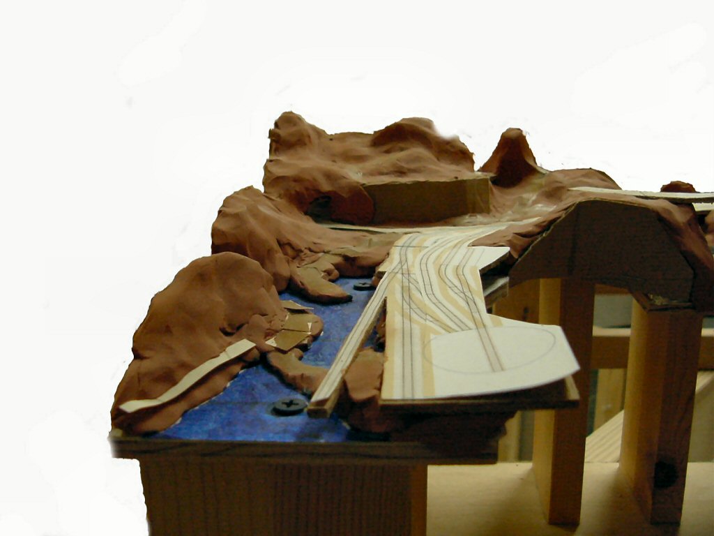
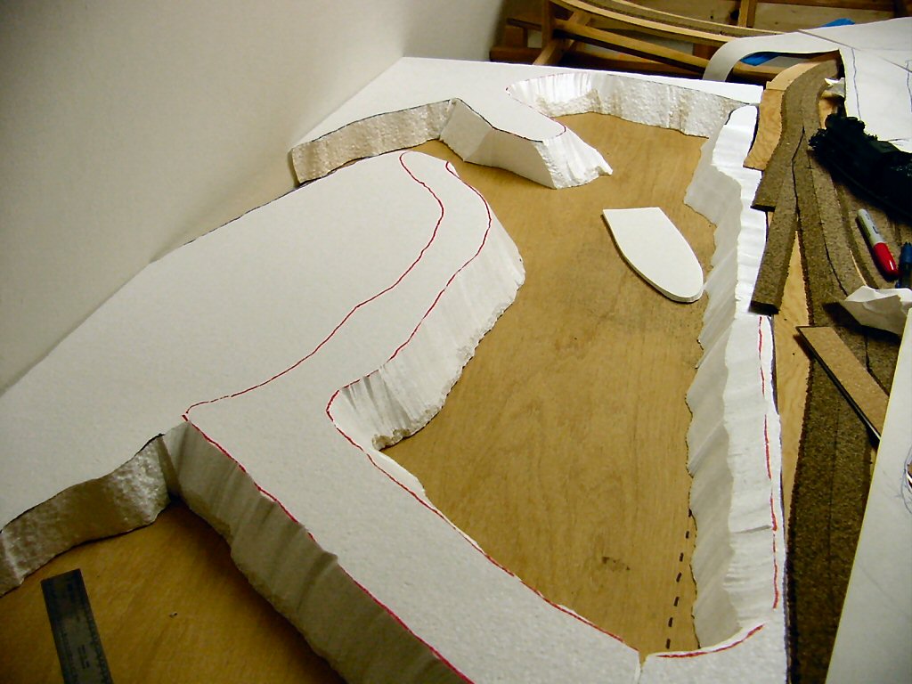
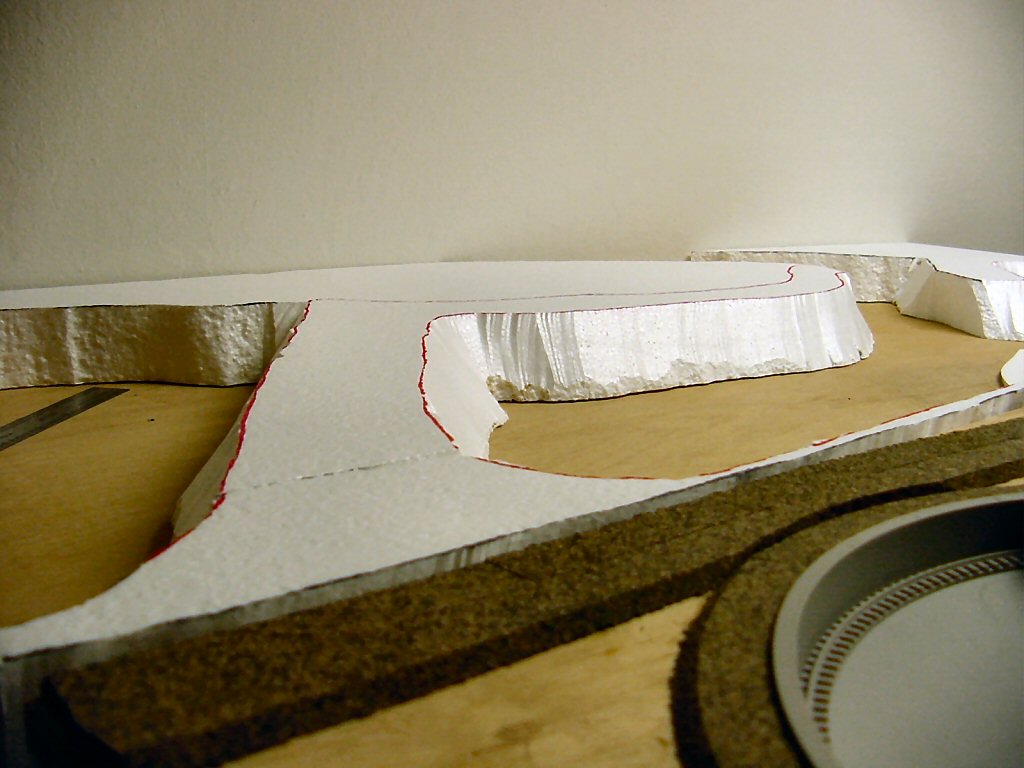
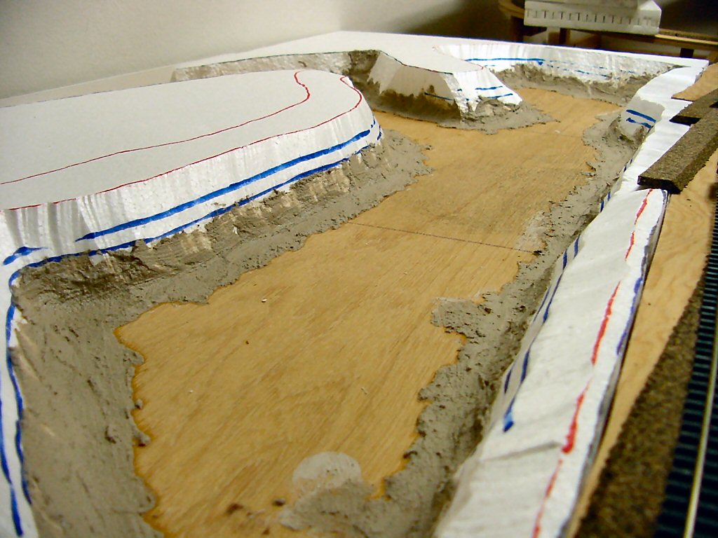
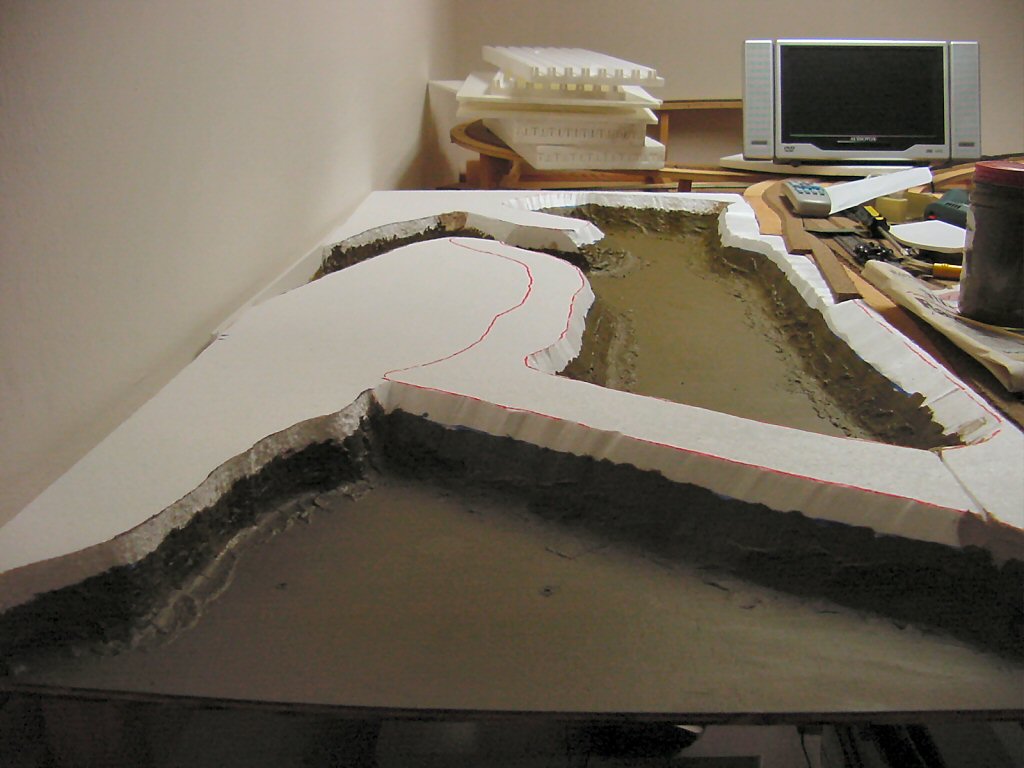
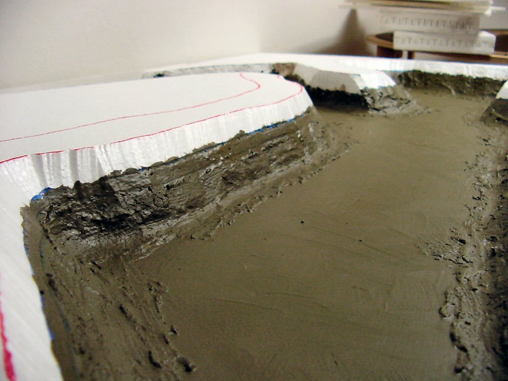
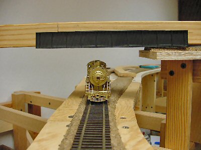
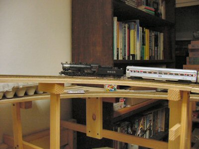
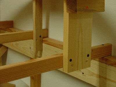
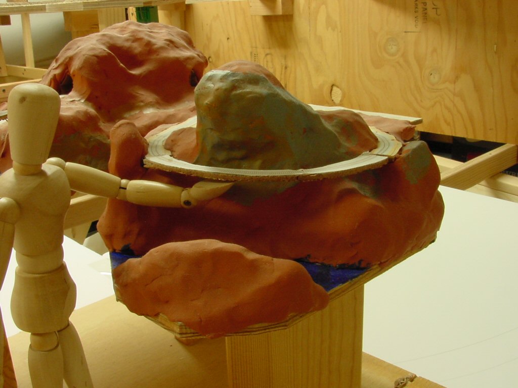
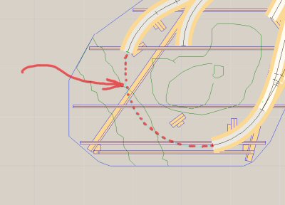
I have my planning model (photo a top of article) to show basic contours of the scenery but now I want to think about how the bridge will actually look in this scenery.

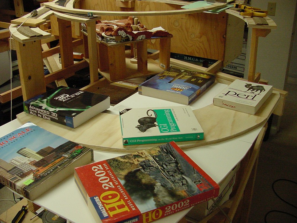
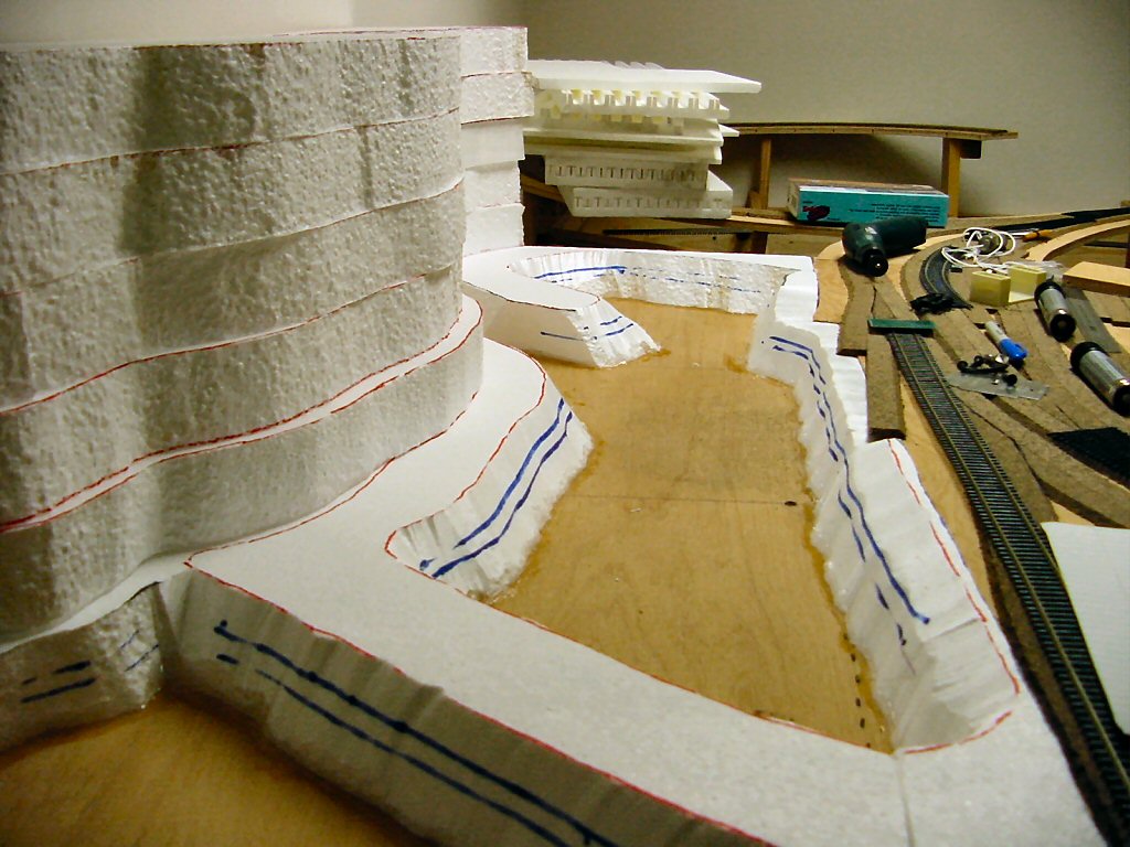
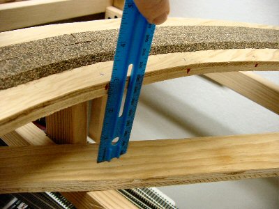
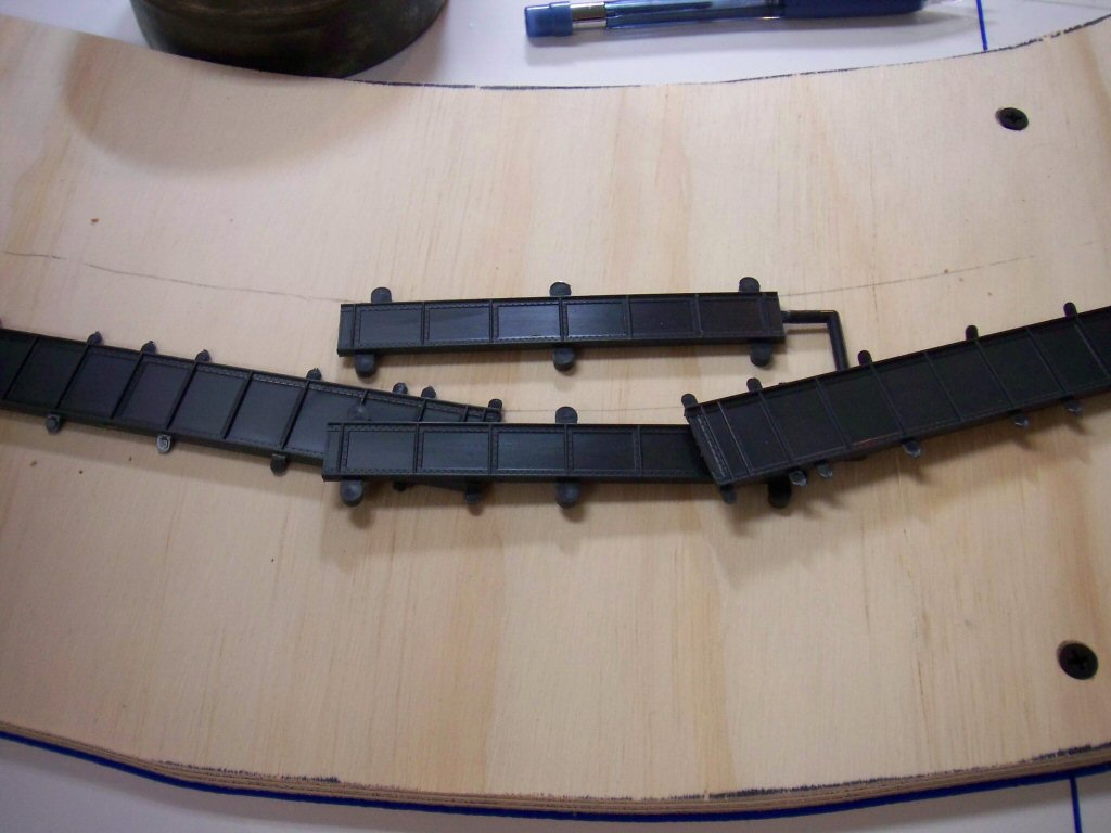
I laid out the pieces of the bridge to get a rough idea how many piers would be needed and roughly where they would be located.

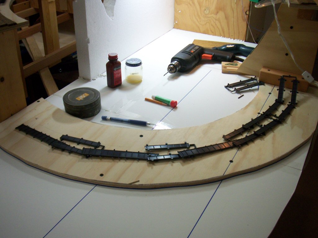
I overlapped the pieces where the towers would be to roughly account for where I was going to shorten the tower spans. This is just for scenery planning so it only needs to be accurate to the nearest inch or so.

Now take this rough layout of parts and use it to guide a sketch of the bridge and the scenery around it.

Acquiring basic drawing skills really helps you build better models. Pelle Søeborg’s article “Visualize your layout” in the November 2006 MR shows a very effective technique you can use when designing your layout. Søeborg shows using a picture of your layout and then use that as a guide to trace in a sketch of how the area will look with scenery. This is a great fast technique.

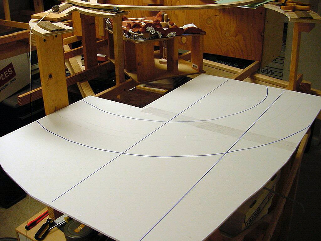
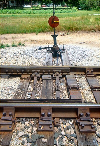
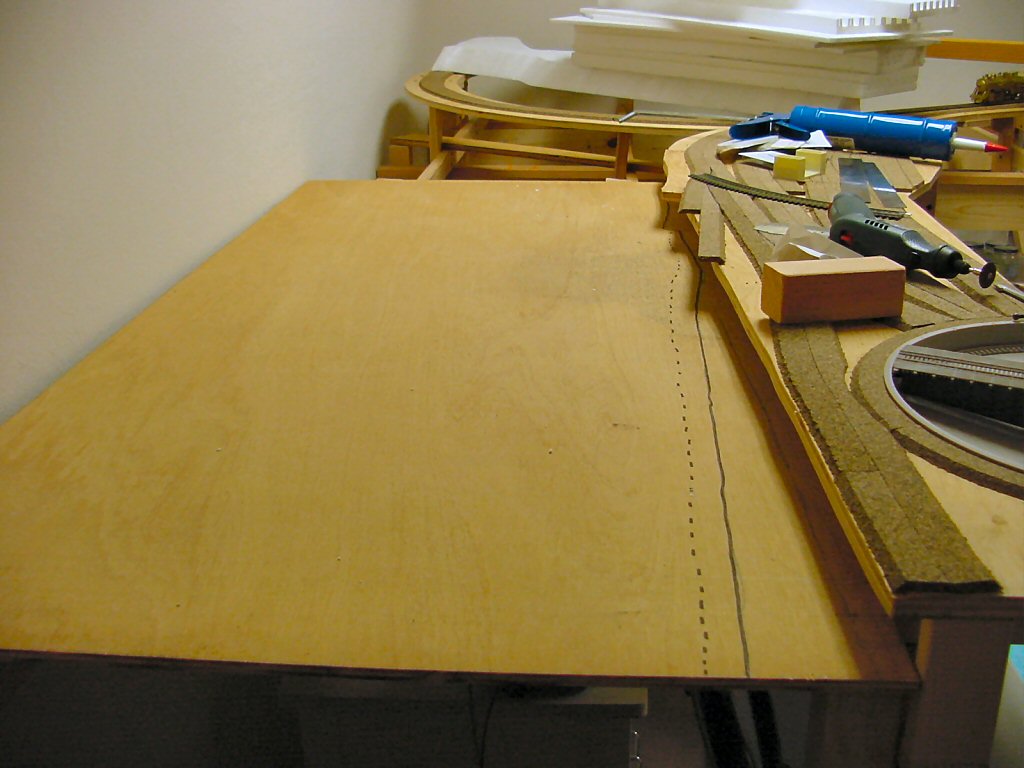
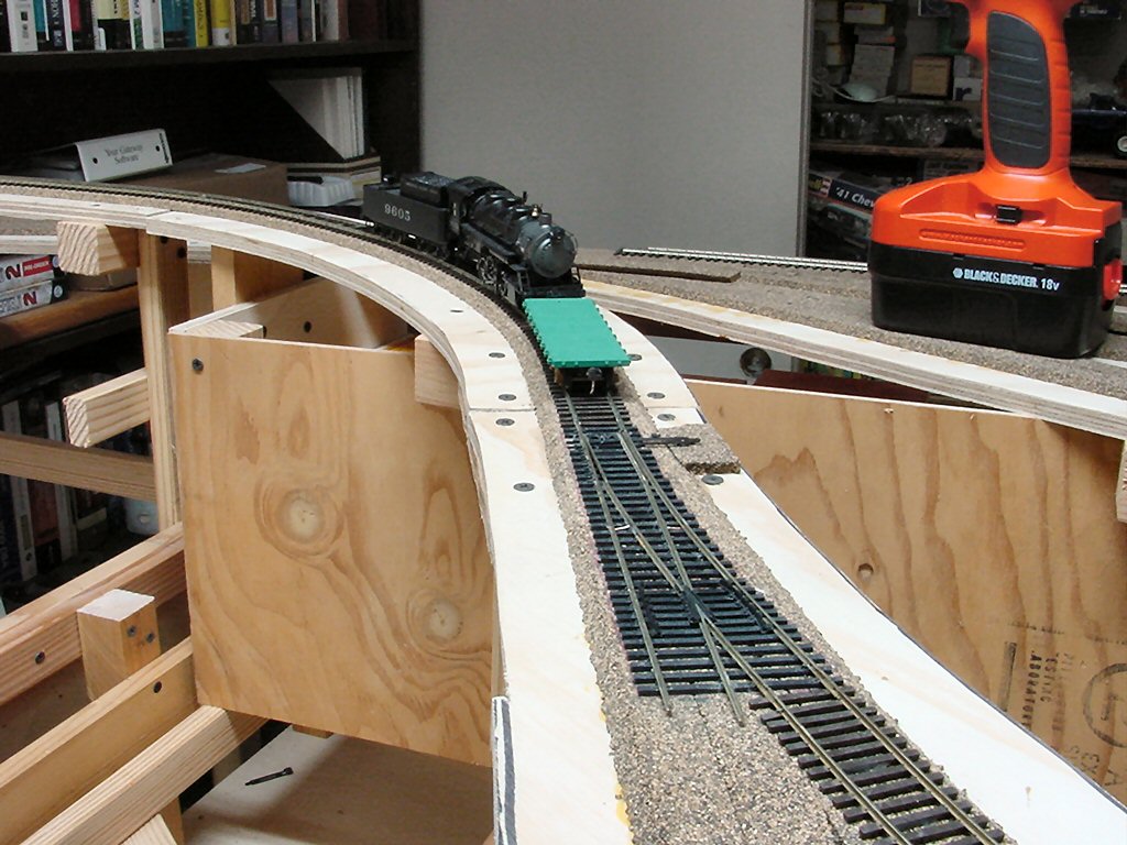
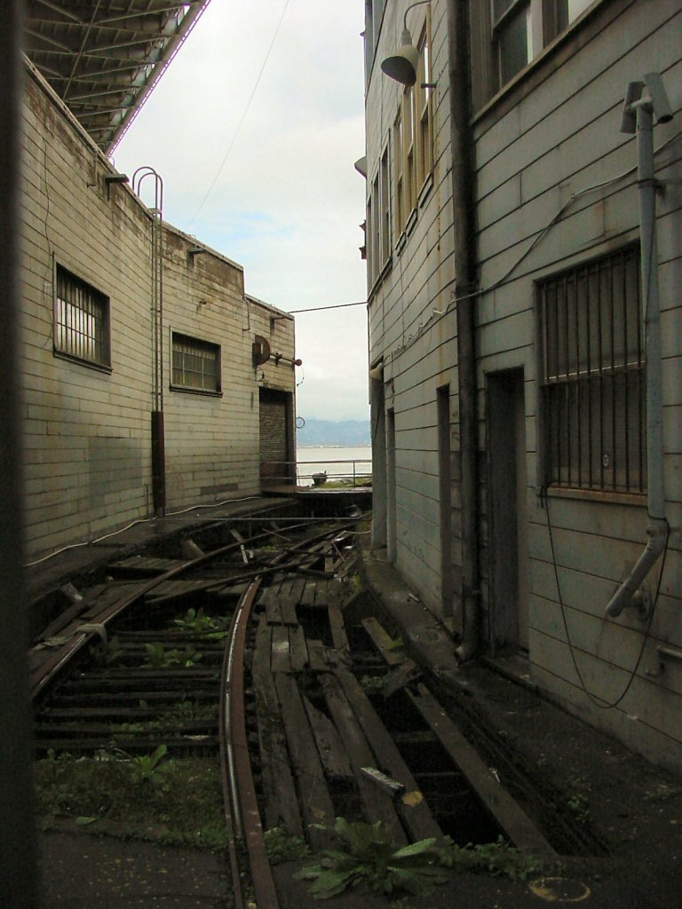
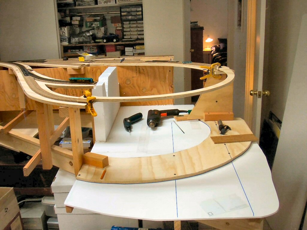
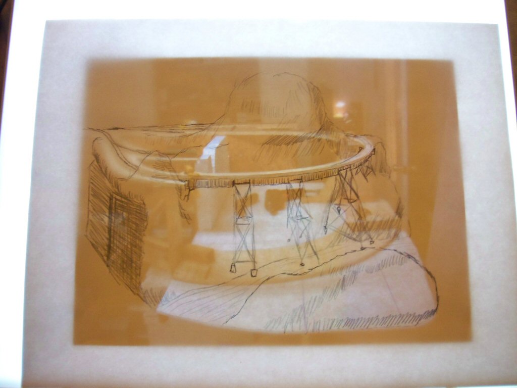
I started with this photo I shot of the area around the bridge.

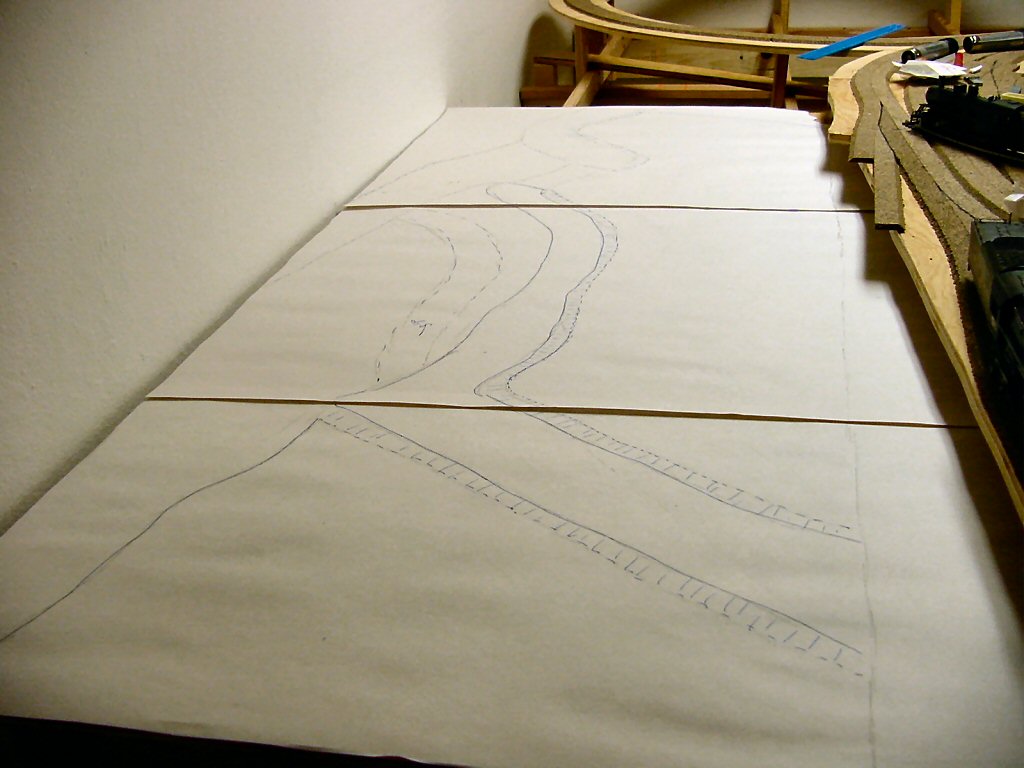
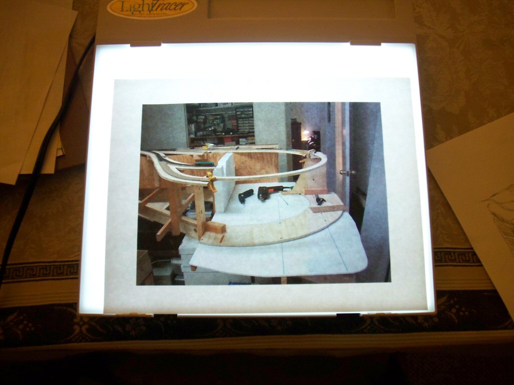
Pelle uses tracing paper but I have a small light table made mainly for tracing and it allows me to use regular paper for my drawings.

Here I’ve taken a print of a photo and placed it on the table.

Then I sketched in the track locations, the bridge and the terrain around the bridge. s

I turn off the light table every now and then to make sure I’ve added everything I wanted.

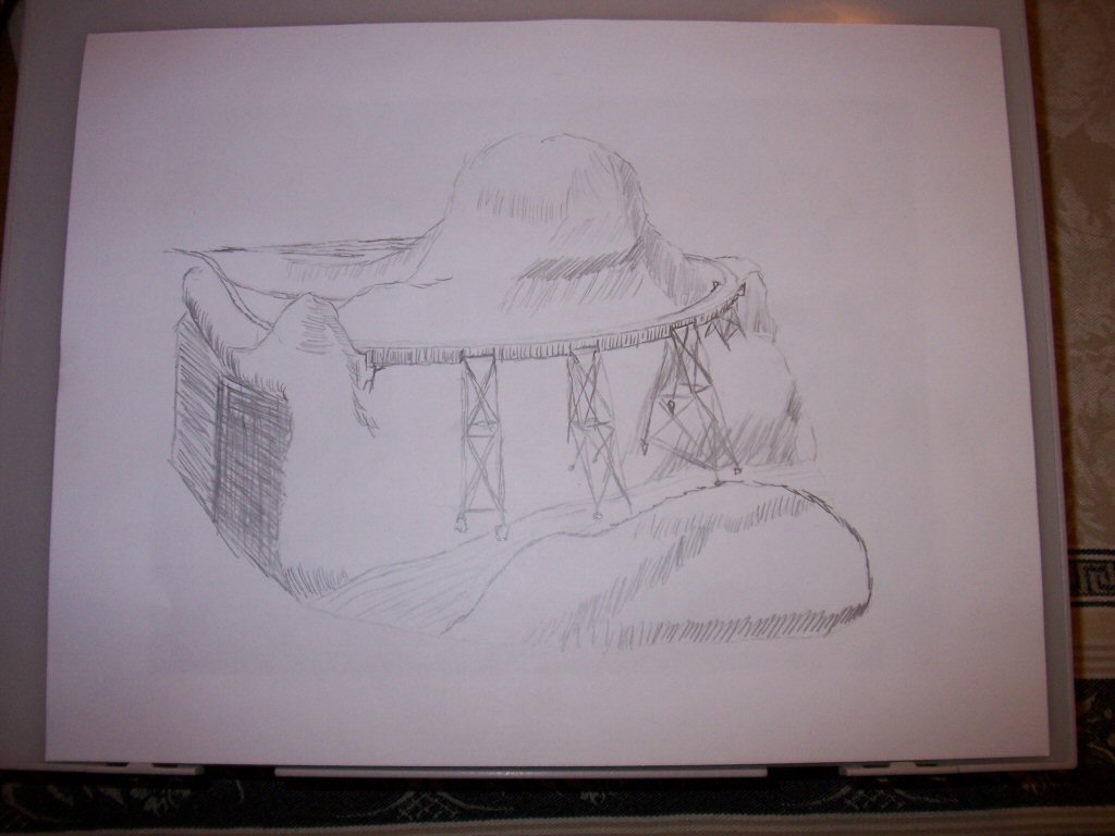
Once I’m done I take the drawing to my scanner and make a high resolution scan.

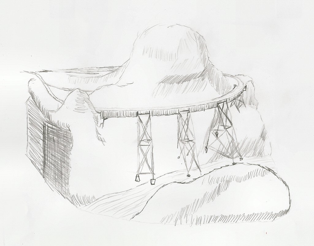
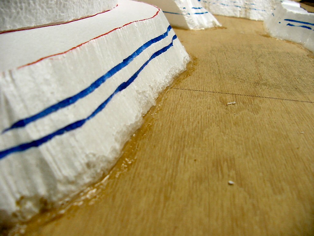
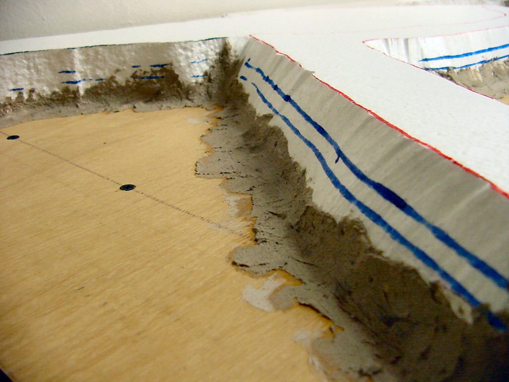
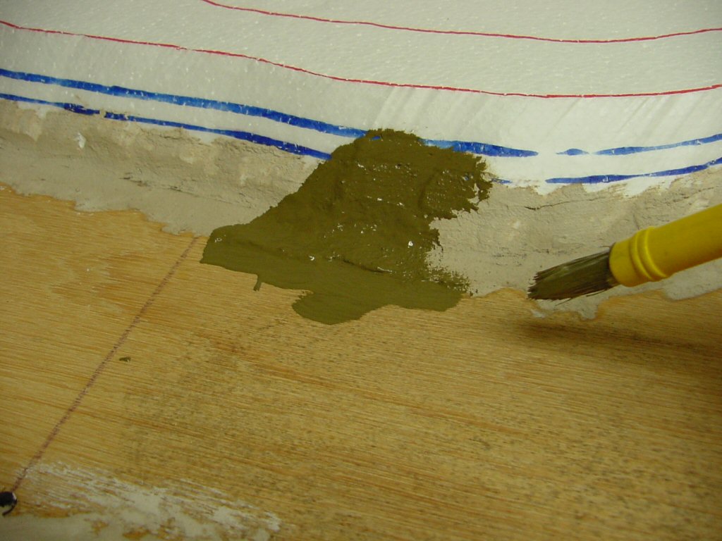
Next is the placement of rock castings and building up foam scenery structure.

A photo of my planning model. Following Malcolm Fulrow’s San Juan Central, one of the return loops spans a deep canyon with a bridge that also completes 118 degrees of the loop.

Here we see the yawning gap where the bridge, river, and a canyon will be built. While I was cutting out roadway I carefully cut a piece of 1/2–inch plywood to be a template for the bridge. Below I’ve clamped it temporarily into place.


I’m building up my scenery from Styrofoam but I decided it would be nice to have a base to work up from so I cut a couple pieces of foam core board to fit the area. Before attaching to the frame I traced out where the underlying studs were and traced out an 8-inch wide semicircle where I would lay down plywood to be a firm footing for the bridge.

Using construction adhesive and drywall screws I attached the foam and the wood to the bench work and weighted everything down with books until the adhesive set.

Using the bridge template I can see that I’m really going to like how the is going to look.

Next step is to get the river and scenery roughed in. Below I’ve placed the planning model below the bridge template.

I need photos and pictures handy when I model. I’m building turnouts right now and I found these two pictures somewhere on the Internet.

These next I took of an industrial siding right outside where I work. I find even a few pictures really helpful to get an idea of weathering and color.

No, the title is not a typo…

I’ve always loved photos of early Tiburon, California. Tiburon grew as the “town at the end of the tracks.” Those tracks belonged to the San Francisco & North Pacific Railroad and later the Northwestern Pacific Railroad.


By the 1920’s Tiburon housed a dense cluster of rail yards, ferry piers, and shops. It was also home to an extremely wild bunch of buildings that grew organically around the end of tracks.

Because the shore near Tiburon was extremely steep, any flat ground was created entirely by filling in the surrounding bay. The railroad did a pretty organized job of it. The townspeople just threw dirt in as needed, drove piles into the remaining shallow water and threw up their structures in a way that would strike terror into the heart of any modern building inspector, fire marshal, or health inspector. Here could be found hotels, cheap housing for railroad workers, bars, cathouses, and stores.

The picture above is looking west. If you looked to the east of the yards and shops you would find much more respectable (but to me less interesting) housing.

I want a town on my layout that captures some of the feel and spirit of Tiburon of this era. However, given my tiny amount of available space I cannot make a serious attempt to model anything about Tiburon of the 1920’s except its “feel.” Additionally I’m going to emphasize, to the point of exaggeration, many of the more colorful aspects of the town so I decided to highlight that by dubbing my version of the town “TiburBon.” Amazing what the simple addition of a “b” does.

Locals insist Tiburbon is pronounced “Tiburr-bon” although visitors seeking a bottle of liquor (found here in abundance despite Prohibition) unfailingly pronounce it “Ti-bourbon.

After looking at maps and photos of Tiburon in the past and walking the streets today (I live in Tiburon) I shaped an idea for the land and water around Tiburbon onto my planning model.


Before I go further with the track work in Tiburbon I decided I’d get a start on the rough scenery here since the town will end up a highly detailed scene behind the tracks and will be easier to work on before the track is laid in.


First I cut a sheet of ¼” plywood to fit which runs the full length of this module. This plywood will be the bottom of the bay. Everything goes up from here.


I laid out paper on the plywood and penciled out shapes guided by what I had on the planning model but I always find that I end up making adjustments once doing it full size. Once I was satisfied I re-traced it in pen.


I cut the paper plan into a templates and cut the shape I needed out of 2” thick bead board sheets. I use a Woodland Scenics hot wire cutter and an electric hot knife to cut Styrofoam. I wear a mask for the fumes and do as much as I can outdoors but as far as I’m concerned heat-cutting foam is the only way to go. Here I’m test fitting them before gluing.

The boat shaped piece of foam board is testing the size of a 60 foot boat.


There’s a gap in the back and eventually I’ll be pouring in my bay water so I laid a piece of  3/16” foam core board there as a dam and glued it down with liquid nails.


The first base level exactly matches the height of the top of the cork roadbed in the adjacent rail yard (good planning on my part). I cut stacks of 2” foam boards up to until I liked the height. I’ll carve these down with the hot knife and glue them down later.


Most materials used to model water (I haven’t decided what I’ll use yet) will seep through any available holes so I sealed the edges with silicon sealant.


The two blue lines were different ideas I had about the water level. Looking at the photos, Tiburon was (and is) built very close to high tide level so I’ve settled on the higher water mark.

I added a fillet of paper mache. This is needed since most paints refuse to stick to the silicone sealant and I want to start to build up the texture.


I painted everything from the high water mark down with my “wet mud” color. This is a base color I had made in latex paint and I use it everywhere under dirt. The color ends up basically olive drab. I’ll probably paint black any areas I want to appear as deep water.


Well, this is all I’m going to fit in on Labor Day weekend.

Yes, I’m still futzing with the track and that darn hill. As I described last time, the hill was too steep and I lowered the end height ¾” and estimated that I had brought the grade down to 6%.

Was it really 6%? I decided to do what I should have done in the first place, really measure the grade. With a ruler and a level-bubble I was able to estimate the grade easily enough, but I could see that the hill was steeper in some places than others. I decided I needed better measurements to not just tell me the grade but tell me how much I should correct elevations along the grade to smooth things out.

Couldn’t I do this with the CAD system? Not really. Something 3rd PlanIt does not do well is vertical transitions and what I’m talking about here is an eight foot ribbon of plywood that eases up to the grade, climbs (and goes around an 18″ radius turn), and finally levels off at the top.

So I got out a ruler and measured the height of the roadbed every three inches to the nearest 1/16th of an inch, entered the measurements into a spreadsheet and found some trouble. The average grade was 5.8% — very close to and below the original estimate. However, that average was made up of sections at about 4% and others at 8%.

Making the speadsheet also made it easy to calculate which risers needed to be adjusted and by how much.

While I was at it I decided to try to pull off another ¾” from the overall climb. To reduce the need to climb I had to change the type of bridge from this:

to a plate girder type bridge like shown below which allows a minimum rail-head to rail-head distance. The bridge shown is a standard Atlas bridge which is not realistic if examined closely — I’ll have to take care with detailing and finishing.

And lose that beautiful Howe truss bridge? No, I’ll simply shorten the wood bridge and it will continue to the left.

 The good news is that the reduction in height reduces this grade to 4.5%. The climb up the other side of the hill becomes 3.7% (same climb but longer run). Now that (admittedly still steep) grade is even with no sudden steeper parts.

Lesson learned: measure, test, measure, and measure again.

The continuing saga of my learning curve building Central Valley Model Works turnout kits. In part one I did the basic assembly.

Now that I’ve added some track around my turnout I can actually run trains over it. The turnout works very well but I did not do a perfect job assembling it. I’m trying to be a very harsh critic of myself because several turnouts on the layout are in tough to reach places and I need to be very clear on proper technique before I build them.

Few things will ruin the enjoyment of your layout more than a turnout in the back corner that keeps derailing everything.

The main things I did wrong are not get the rails tightly enough around the frog and I did not snug the guard rails close enough to the stock rails.

Using an NMRA standards gauge you can see that the track gauge is correct but the width of the flangeway is not correct. For those not familiar with this tool the tabs highlighted in red show how wide the flangeway should be.

Given the way the frog casting works, snugging up the guard rail (the black plastic rail on the left) will be the easy fix.

One thing to watch is to make sure that the frog rails (the rails that are attached in a “V”) are pushed as far forward into the frog casting as possible. However, this can be taken too far since the geometry is such that if pushed too far forward the track gauge will become too narrow.

An easy fix: make sure the closure rails (by the arrow on the right)

are really tight to the frog casting. Note that the closure rail on the left of the frog (to the left of the RIGHT arrow) is loose. The closure rail on the right of the frog is pretty good.

Despite these obvious flaws the turnout works flawlessly (if a bit bumpy for some pieces of rolling stock) so I have to admit that the Central Valley design seems to be quite forgiving.

So I finally got some track laid up hill from my first turnout. Where have I been? My day job is building a piece of Microsoft’s latest operating system and we had a BIG deadline…

Anyhoo, as soon as I had two whole pieces of flex track down I did what every red-blooded model railroader does: hooked up a power pack and ran some trains!!

The good news: the track is nice and smooth and the one turnout works flawlessly despite obvious imperfections (see other post).

Too Steep

The bad news: I had been worried about the grade uphill from the turnout. On the plan it works out to about 5.8% but that’s with no vertical transitions. With the transitions (effectively the distance it takes for 1/2″ plywood to smoothly bend to the grade) the same height is being gained in less distance — so the real hill is steeper.

Honestly, I knew all this going in, but I had not measured the grade. When I ran a train I found that my thumping Life-Like USRA 0-8-0 swticher could not pull even two free-rolling Athearn 75’ shorty passenger cars up the grade (not that I ever plan on using those cars on my 1920′s layout but they were handy…). Oops. The grade is more like 7%-plus!

I had to lower the grade. Looking at the layout, the height of the grade had been determined by the height needed to clear over the return loop with clearance. I had arbitrarily chosen a pretty high clearance at that point.

However, I needed to reduce the height climbed as much as possible so I made a template based on the Howe truss bridge that will be used at that point and measured how much I could bring the upper track down while still clearing the NMRA recommended height.

I was able to reduce the height by 3/4 of an inch. That may not seem like much but the total climb was 5″ so that’s a 15% reduction. With the reduced grade comes a reduction in the needed vertical transitions so this brings the grade down to more like 6%. Still severe but more workable — and more like what I had planned.

How do you lower twelve feet of roadbed? Unscrew the risers, clamp at the new (lower) height, and re-screw them. Not too pretty but nobody will see this once the scenery is up.

Note that RAISING the track would be MUCH more work.

Can the 0-8-0 get the two cars up the grade now? BARELY. Luckily, my designed train length is four 40′ cars plus a caboose and the prototype NWP often needed doubling on their frequent short-steep hills.

Waterfronts have always been interesting to me since they are often funky and usually have lots of history visible.

I live just across the bay from San Francisco and a couple weeks ago I took the ferry over to the waterfront and took some pictures.

The tracks on the San Francisco waterfront were operated by the State Belt Railroad and were standard gauge with a large portion dual-gauged with 3 foot trackage to handle narrow gauge cars ferried over from the south-east bay and north bay.

Here’s a nice bit of old pier left. There are railroad tracks on it as well. This is the remains of Pier 22-1/2. That little bridge in the background is the San Francisco Oakland Bay Bridge. A beautiful bridge in its own right but forever outshone by the nearby Golden Gate bridge.

If you have the free Google Earth application (HIGHLY recommended) you can go right to this location and follow along the next few photos by clicking on the location link here: San Francisco Fireboat 1 Phoenix

Close up showing the girder style (like street traction) track in the old pier.

This bit of pier is near the San Francisco Fire Department’s Fireboat Station No. 1 station which is itself built on a pier. The fireboat was away that morning.

Just south of the Bay Bridge is this tight little space between buildings with the track intact. This is the north side of Pier 26.

A little further south is Red’s Java House. When I first saw this building ten years ago it was very funky. Imagine it without the spiffy new paint.

« Previous PageNext Page »