Mon 11 Oct 2010
Remembering Mike Stokinger
Posted by Daniel Swearingen under Model Railroading[3] comments / Leave a comment

Published in San Francisco Chronicle on October 17, 2010
Mike Stokinger A long time railroad buff and friend of many, died Sunday September 26th, he was 56 years old. There will be a gathering of friends to celebrate Mike’s life at the Josephine Randall Museum on Wednesday, October 20 from 6:30 to 9:00 pm.
From the Golden Gate Model Railroad Club blog:
Last week, the Golden Gate Model Railroad Club lost a long time member and friend: Mike Stokinger. Mike was not only an active participant with the GGMRC but also a great person and very much involved with building the organization and ties with the model railroad community and friends of the GGMRC. Help us remember him and his love of model trains by stopping by to see the passion that he lived for.

From The Peter Pan Express in April 1997 Salon
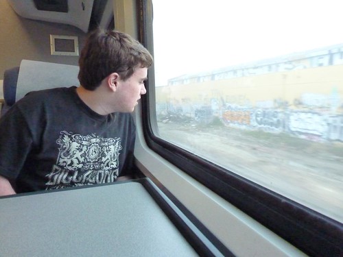
I recall Mike Stokinger, the genial treasurer of the Golden Gate Model Railroad Club, who described his love for trains in such different terms. “There’s something very soothing, very musical about them. When you’re in a train, you’re in a cozy enclosed space, you’ve got movement, this hypnotic hum of sound and it’s almost like being in the womb.”
My memories of Mike
I grew up in Noe Valley in the 1970’s and took classes at the Randall Museum. Open houses at the GGMRC were rare and big events. The line typically ran down Museum Way and the wait seemed like hours. I grew up, moved away, school, etc. but made it back to the Bay Area in 1996 and was a member of the GGMRC for a few years in the late 90′s.
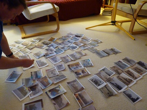
Mike was a great guy. We had him over for dinner one night and he brought over a projector, a screen, and 4-5 slide carousels (several hundred slides) of his recent train trip to Chicago on Amtrak as well as photos from his trip to China. Mike managed to make a three hour slide show very entertaining. Mike was always passionate about passenger trains and I fondly recall his long strings of name-train cars snaking around the layout. I’m very sad and sorry he is gone and agree that he will be missed.